MAN B&W 8.08
Page of
MAN Diesel
MAN B&W ME/ME-B/MEC/MEGI engines, ME Engine Selection Guide 198 48 297.2
Hydraulic oil backushing
The special suction arrangement for purier suc-
tion in connection with the ME engine (Integrated
system).
The back-ushing oil from the self cleaning 0 µm
hydraulic control oil lter unit built onto the engine
is contaminated and it is therefore not expedient
to lead it directly into the lubricating oil sump tank.
The amount of back-ushed oil is large, and it
is considered to be too expensive to discard
it. Therefore, we suggest that the lubricating
oil sump tank is modied for the ME engines in
order not to have this contaminated lubricating
hydraulic control oil mixed up in the total amount
of lubricating oil. The lubricating oil sump tank is
designed with a small ‘back-ushing hydraulic
control oil drain tank’ to which the back-ushed
hydraulic control oil is led and from which the lu-
bricating oil purier can also suck.
This is explained in detail below and the principle
is shown in Fig. 8.08.0. Three suggestions for the
arrangement of the drain tank in the sump tank
are shown in Fig. 8.08.02 illustrates another sug-
gestion for a back-ushing oil drain tank.
The special suction arrangement for the purier is
consisting of two connected tanks (lubricating oil
sump tank and back-ushing oil drain tank) and
of this reason the oil level will be the same in both
tanks, as explained in detail below.
The oil level in the two tanks will be equalizing
through the ‘branch pipe to back-ushing oil drain
tank’, see Fig. 8.08.0. As the pipes have the
same diameters but a different length, the resis-
tance is larger in the ‘branch pipe to back-ushing
oil drain tank’, and therefore the purier will suck
primarily from the sump tank.
The oil level in the sump tank and the back-ush-
ing oil drain tank will remain to be about equal be-
cause the tanks are interconnected at the top.
When hydraulic control oil is back-ushed from
the lter, it will give a higher oil level in the back-
ushing hydraulic control oil drain tank and the
purier will suck from this tank until the oil level is
the same in both tanks. After that, the purier will
suck from the sump tank, as mentioned above.
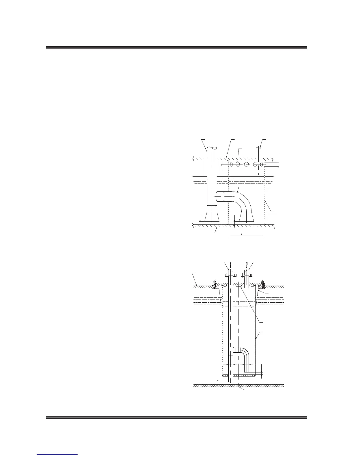
Fig. 8.08.01: Backushing servo oil drain tank
178 52 518.1
Fig. 8.08.02: Alternative design for the
backushing servo oil drain tank
178 52 496.1
This special arrangement for purier suction will
ensure that a good cleaning effect on the lubrica-
tion oil is obtained.
If found protable the back-ushed lubricating oil
from the main lubricating oil lter (normally a 50 or
40 µm lter) can also be returned into the special
back-ushing oil drain tank.

 Loading...


