S90ME-C, K90ME-C, S80ME-C 198 43 81-3.1
MAN B&W Diesel A/S 6.04
Page 2 of 12
The derated cooler capacities may then be found
by means of following equations:
Q
air, M
=Q
air, L
1
x (Q
air%
/ 100)
Q
jw, M
=Q
jw, L
1
x (Q
jw%
/ 100)
Q
lub, M
=Q
lub, L
1
x (Q
lub%
/ 100)
and for a central cooling water system the central
cooler heat dissipation is:
Q
cent,M
=Q
air,M
+ Q
jw,M
+ Q
lub,M
Pump capacities
The pump capacities given in the ‘List of Capaci-
ties’ refer to engines rated at nominal MCR (L
1
). For
lower rated engines, only a marginal saving in the
pump capacities is obtainable.
To ensure proper lubrication, the lubricating oil pump
must remain unchanged.
Also, the fuel oil circulating and supply pumps should
remain unchanged.
In order to ensure reliable starting, the starting air
compressors and the starting air receivers must also
remain unchanged.
The jacket cooling water pump capacity is relatively
low. Practically no saving is possible, and it is there-
fore unchanged.
Seawater cooling system
The derated seawater pump capacity is equal to
the sum of the below found derated seawater flow
capacities through the scavenge air and lube oil
coolers, as these are connected in parallel.
The seawater flow capacity for each of the scav-
enge air, lube oil and jacket water coolers can be
reduced proportionally to the reduced heat dissi-
pations found in Figs. 6.04.01, 6.04.02 and 6.04.03,
respectively i.e. as follows:
V
sw,air,M
=V
sw,air,L
1
x (Q
air%
/ 100)
V
sw,lub,M
=V
sw,lub.L
1
x Q
lub%
/ 100)
V
sw,jw,M
=V
sw,lub,M
However, regarding the scavenge air cooler(s), the
engine maker has to approve this reduction in order
to avoid too low a water velocity in the scavenge air
cooler pipes.
As the jacket water cooler is connected in series
with the lube oil cooler, the seawater flow capacity
for the latter is used also for the jacket water cooler.
Central cooling water system
If a central cooler is used, the above still applies,
but the central cooling water capacities are used
instead of the above seawater capacities. The sea-
water flow capacity for the central cooler can be
reduced in proportion to the reduction of the total
cooler heat dissipation, i.e. as follows:
V
cw,air,M
=V
cw,air,L
1
x (Q
air%
/ 100)
V
cw,lub,M
=V
cw,lub,L
1
x (Q
lub%
/ 100)
V
cw,jw,M
=V
cw,lub,M
V
cw,cent,M
=V
cw,air,M
+ V
cw,lub,M
V
sw,cent,M
=V
sw,cent,L
1
x Q
cent,M
/ Q
cent,L
1
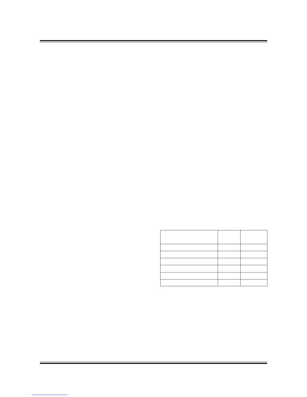
Pump pressures
Irrespective of the capacities selected as per the
above guidelines, the below-mentioned pump heads
at the mentioned maximum working temperatures
for each system shall be kept:
Fuel oil supply pump 4 100
Fuel oil circulating pump 6 150
Lubricating oil pump 4.6 70
Seawater pump 2.5 50
Central cooling water pump 2.5 80
Jacket water pump 3.0 100
Flow velocities
For external pipe connections, we prescribe the fol-
lowing maximum velocities:
Marine diesel oil ......................................... 1.0 m/s
Heavy fuel oil.............................................. 0.6 m/s
Lubricating oil............................................. 1.8 m/s
Cooling water ............................................. 3.0 m/s
Max. working
temp. °C
Pump
head bar

 Loading...


