MAN B&W 8.06
Page 2 of 2
MAN Diesel
MAN B&W S80MCC7/8, S80MEC7/8 198 42 507.1
Note:
When calculating the tank heights, allowance has
not been made for the possibility that a quantity of
oil in the lubricating oil system outside the engine
may be returned to the bottom tank, when the
pumps are stopped.
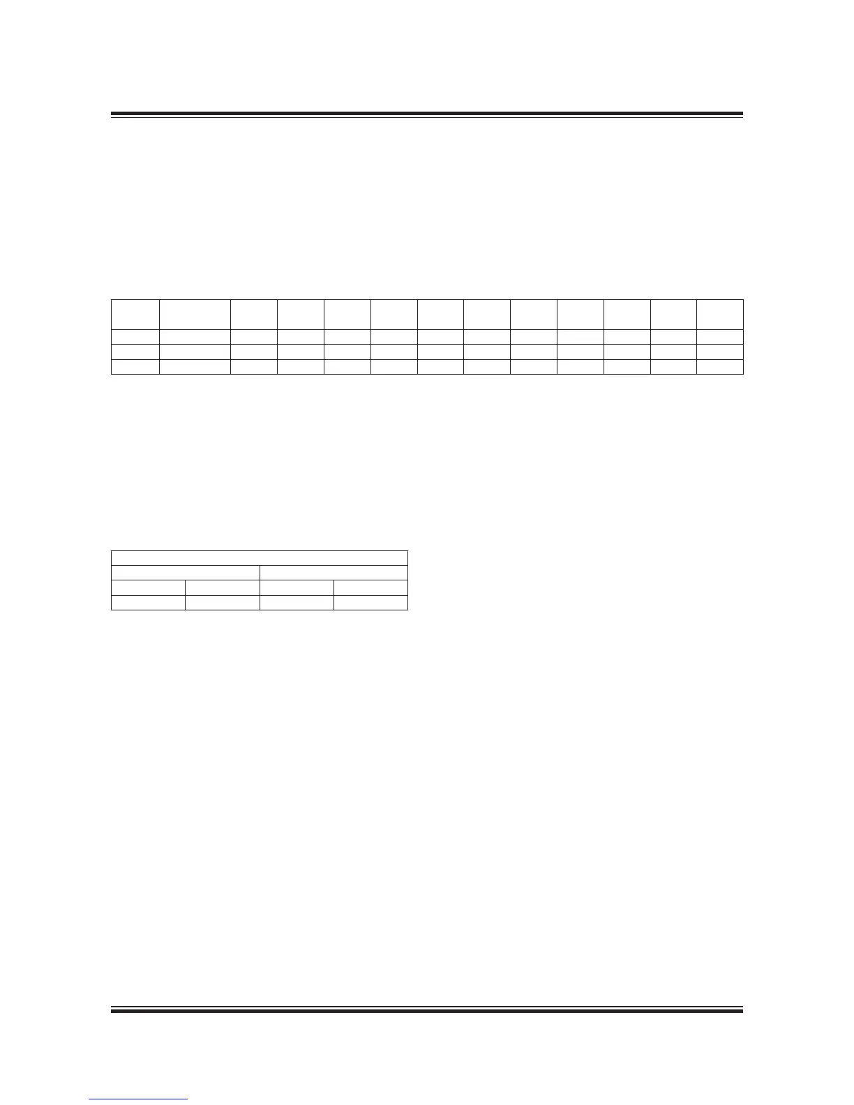
The lubricating oil bottom tank complies with the
rules of the classication societies by operation
under the following conditions:
Angle of inclination, degrees
Athwartships Fore and aft
Static Dynamic Static Dynamic
5
22.5 5 7.5
Cylin-
der No.
Drain at
cylinder No.
D0 D1 D3 H0 H1 H2 H3 W L OL Qm
3
6 25 300 2x450 2x225 ,270 450 90 400 600 9,600 ,70 39.0
7 257 325 2x450 2x225 ,30 450 90 400 700 ,200 ,20 47.0
8 2-5-7 350 2x475 2x250 ,390 475 95 600 800 2,800 ,290 57.3
Table 8.06.01b: Lubricating oil tank, with cofferdam
If the system outside the engine is so designed
that an amount of the lubricating oil is drained
back to the tank, when the pumps are stopped,
the height of the bottom tank indicated in Table
8.06.0b has to be increased to include this quan-
tity. If space is limited, however, other solutions
are possible.
Lubricating oil tank operating conditions

 Loading...


