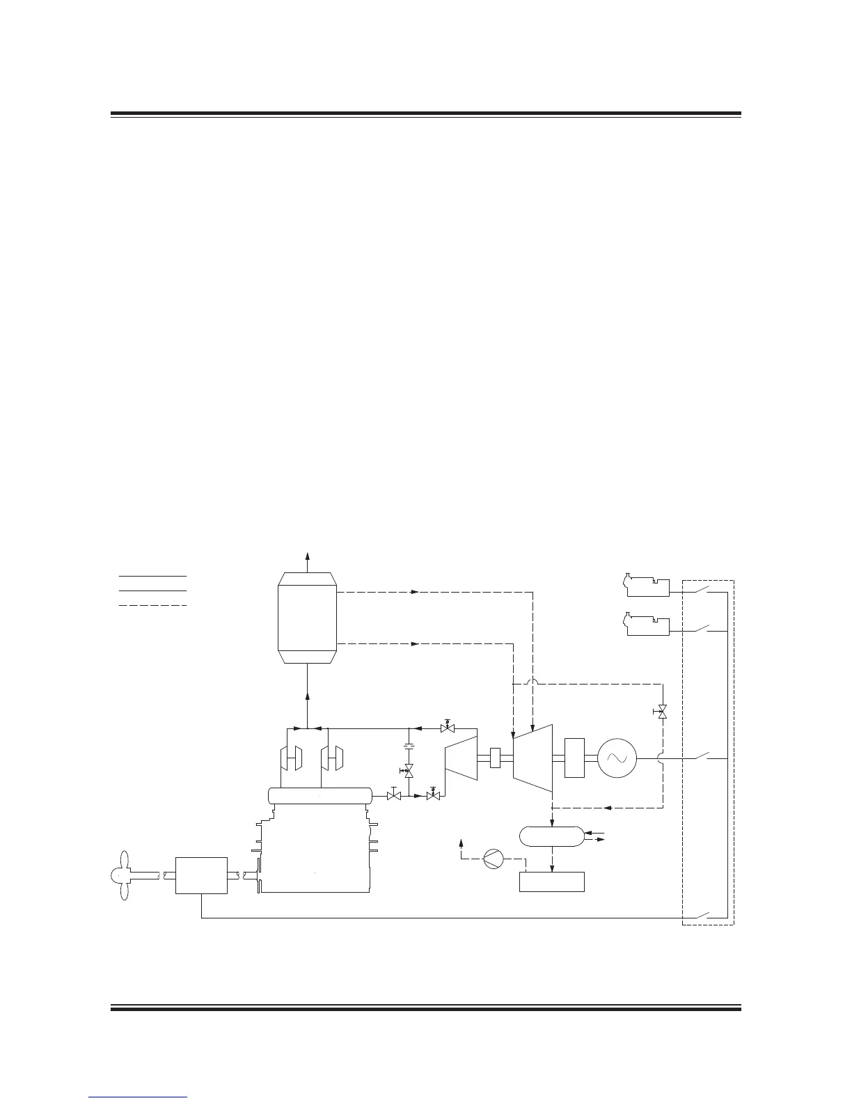
Combined Turbines
Because the installation of the power turbine also
will result in an increase of the exhaust gas tem-
perature after the turbochargers, it is possible to
install both the power turbine, the larger boiler
and steam turbine on the same engine. This way,
the energy from the exhaust gas is utilised in the
best way possible by today’s components.
When looking at the system with both power and
steam turbine, quite often the power turbine and
the steam turbine are connected to the same
generator. In some cases, it is also possible to
have each turbine on a separate generator. This
is, however, mostly seen on stationary engines,
where the frequency control is simpler because of
the large grid to which the generator is coupled.
For marine installations the power turbine is, in
most cases, connected to the steam turbine via a
gearbox, and the steam turbine is then connected
to the generator. It is also possible to have a gen-
erator with connections in both ends, and then
connect the power turbine in one end and the
steam turbine in the other. In both cases control of
one generator only is needed.
For dimensions of a typical system see
Fig. 4.05.06.
As mentioned, the systems with steam turbines
require a larger boiler to be installed. The size
of the boiler system will be roughly three to four
times the size of an ordinary boiler system, but
the actual boiler size has to be calculated from
case to case.

 Loading...


