MAN B&W 17.05
Page of
MAN Diesel
MAN B&W ME/ME-B/MEC/MEGI engines 198 45 170.5
As the deection shape for the Htype is equal
for each cylinder the N
th
order Htype guide force
moment for an Ncylinder engine with regular r-
ing order is:
N x M
H(one cylinder)
For modelling purposes the size of the forces in
the force couple is:
Force = M
H
/L [kN]
where L is the distance between crankshaft level
and the middle position of the crosshead guide
(i.e. the length of the connecting rod.)
As the interaction between engine and hull is at
the engine seating and the top bracing positions,
this force couple may alternatively be applied in
those positions with a vertical distance of (L
Z
).
Then the force can be calculated as:
Force
Z
= M
H
/L
Z
[kN]
Any other vertical distance may be applied, so as
to accomodate the actual hull (FEM) model.
The force couple may be distributed at any
number of points in the longitudinal direction. A
reasonable way of dividing the couple is by the
number of top bracing and then applying the forc-
es at those points.
Force
Z, one point
= Force
Z, total
/N
top bracing, total
[kN]
Xtype Guide Force Moment (M
X
)
The Xtype guide force moment is calculated
based on the same force couple as described
above. However as the deection shape is twist-
ing the engine each cylinder unit does not contrib-
ute with an equal amount. The centre units do not
contribute very much whereas the units at each
end contributes much.
A socalled ‘Bimoment’ can be calculated (Fig.
17.05.01):
‘Bimoment’ = Σ [forcecouple(cyl.X) x distX]
in kNm
2
The Xtype guide force moment is then dened
as:
M
X
= ‘BiMoment’/L kNm
For modelling purpose the size of the four (4) forc-
es can be calculated:
Force = M
X
/L
X
[kN]
where:
L
X
is the horizontal length between ‘force points’
Similar to the situation for the Htype guide force
moment, the forces may be applied in positions
suitable for the FEM model of the hull. Thus the
forces may be referred to another vertical level L
Z
above crankshaft centre line. These forces can be
calculated as follows:
Force
Z, one point
=
M
x
x L
_____
L x L
[kN]
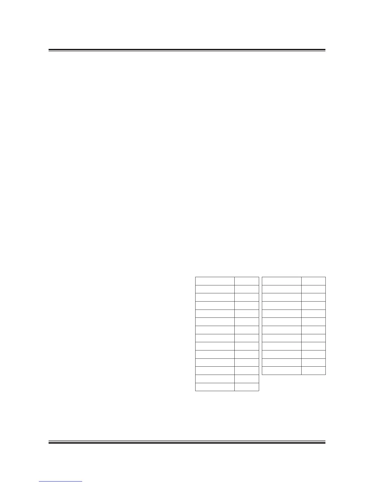
In order to calculate the forces it is necessary
to know the lengths of the connecting rods = L,
which are:
Engine Type L in mm
K108MEC6 ,400
K98ME6/7 ,220
K98MEC6/7 ,090
S90MEC7/8 ,270
K90ME9 ,20
K90ME-C9 ,120
K90MEC6 ,159
S80MEC9 ,450
S80MEC7/8 ,280
K80MEC9 2,975
K80MEC6 2,920
S70ME-C7/8 2,870
S70MEGI7/8 2,870
Engine Type L in mm
L70MEC7/8 2,660
S65MEC8 2,70
S65MEGI8 2,70
S60MEC7/8 2,460
S60MEGI7/8 2,460
L60MEC7/8 2,280
S50MEC7/8 2,050
S50ME-B9 2,114
S50ME-B8 2,050
S40ME-B9 1,770
S5ME-B9
1,550

 Loading...


