MAN B&W 6.04
Page 6 of 12
MAN Diesel
MAN B&W S50MC/MC-C-TII, S46MC-C-TII, S42MC-TII,
S40MC-C-TII, S35MC/MC-C-TII, L35MC-TII, S26MC-TII
198 71 42-2.0
Jacket Cooling Water Temperature Control
When using a normal freshwater generator of the
singleeffect vacuum evaporator type, the fresh-
water production may, for guidance, be estimated
as 0.03 t/24h per 1 kW heat, i.e.:
M
fw
= 0.03 x Q
jw
t/24h 15%/0% [3]
where
M
fw
is the freshwater production in tons per 24
hours
and
Q
jw
is to be stated in kW
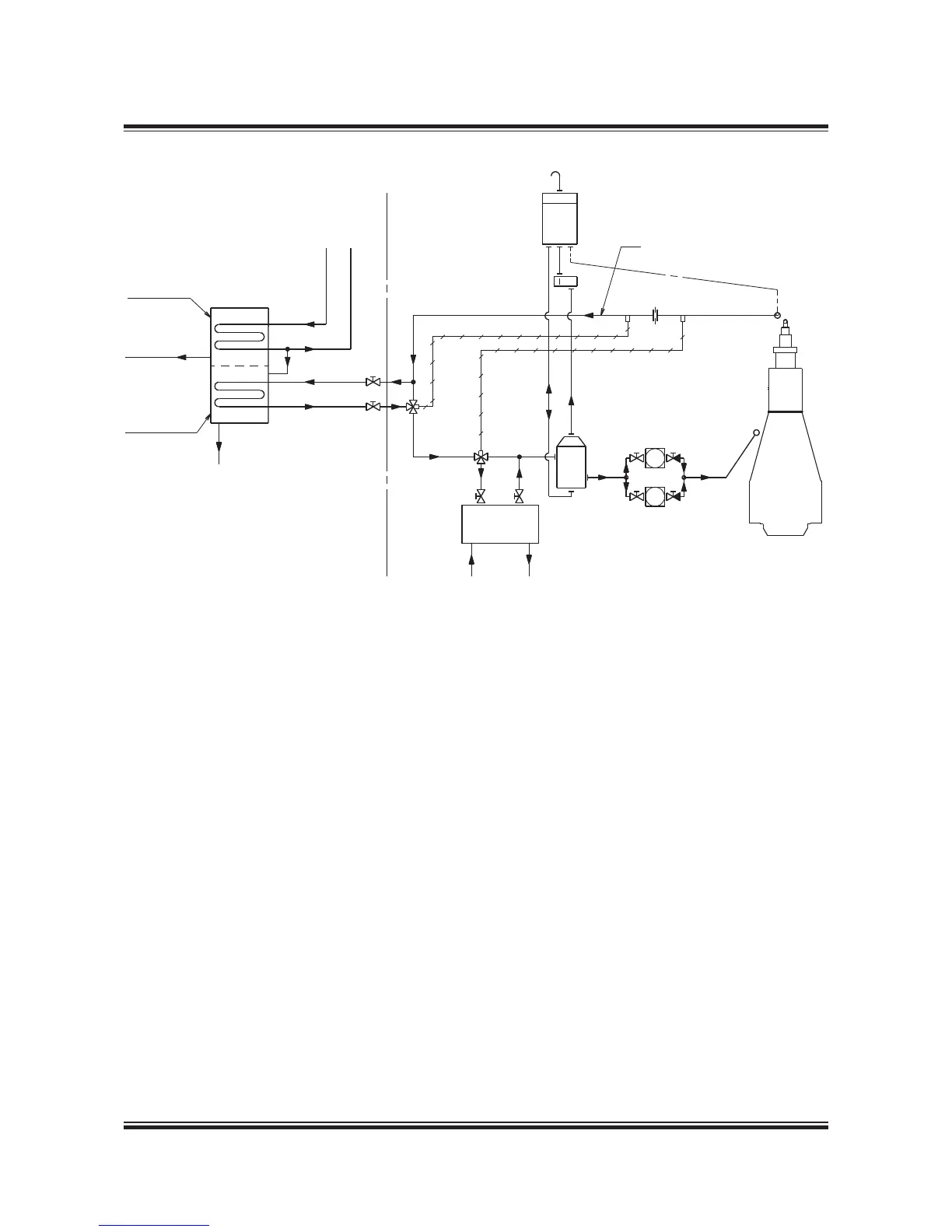
Valve A: ensures that T
jw
< 80° C
Valve B: ensures that T
jw
> 80 – 5° C = 75° C
Valve B and the corresponding bypass may be omitted if, for example, the freshwater generator is equipped with an automatic
start/stop function for too low jacket cooling water temperature
If necessary, all the actually available jacket cooling water heat may be utilised provided that a special temperature control system
ensures that the jacket cooling water temperature at the outlet from the engine does not fall below a certain level
Fig. 6.04.05: Freshwater generators. Jacket cooling water heat recovery flow diagram
178 23 700.0
If necessary, all the actually available jacket cool-
ing water heat may be used provided that a special
temperature control system ensures that the jacket
cooling water temperature at the outlet from the
engine does not fall below a certain level. Such a
temperature control system may consist, e.g., of a
special bypass pipe installed in the jacket cooling
water system, see Fig. 6.04.05, or a special builtin
temperature control in the freshwater generator,
e.g., an automatic start/stop function, or similar.
If such a special temperature control is not applied,
we recommend limiting the heat utilised to maxi-
mum 50% of the heat actually available at specified
MCR, and only using the freshwater generator at
engine loads above 50%. Considering the cooler
margin of 10% and the minus tolerance of 15%,
this heat corresponds to 50 x(1.000.15)x0.9 = 38%
of the jacket water cooler capacity Q
jw,M
used for
dimensioning of the jacket water cooler.

 Loading...


