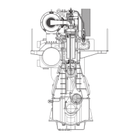
MAN B&W l35MC6
MAN B&W Contents
Chapter Section
MAN Diesel
5 Installation Aspects
Space requirements and overhaul heights 5.01 1984375-4.6
Space requirement 5.02 1985787-0.0
Crane beam for overhaul of turbochargers 5.03 1984490-3.2
Crane beam for turbochargers 5.03 1984853-5.6
Engine room crane 5.04 1985749-9.0
Overhaul with Double-Jib crane 5.04 1984534-8.4
Double-Jib crane 5.04 1984541-9.2
Engine outline, galleries and pipe connections 5.05 1984715-8.3
Engine and gallery outline 5.06 1986360-8.0
Centre of gravity 5.07 1986649-8.0
Water and oil in engine 5.08 1985683-8.0
Engine pipe connections 5.09 1986363-3.0
Counterflanges 5.10 1986362-1.0
Counterflanges, Connection D 5.10 1986670-0.2
Counterflanges, Connection E 5.10 1987027-3.0
Engine seating and holding down bolts 5.11 1984176-5.7
Epoxy chocks arrangement 5.12 1985843-3.0
Engine seating profile 5.12 1985831-3.0
Engine top bracing 5.13 1985881-5.0
Mechanical top bracing 5.14 1984764-8.3
Hydraulic top bracing arrangement 5.15 1984792-2.0
Components for Engine Control System 5.16 1986030-2.0
Shaftline earthing device 5.17 1984929-2.4
MAN Diesels Alpha Controllable Pitch (CP) propeller 5.18 1984695-3.5
Hydraulic Power Unit for Alpha CP propeller 5.18 1985320-8.2
Alphatronic 2000 Propulsion Control System 5.18 1985322-1.2
6 List of Capacities: Pumps, Coolers & Exhaust Gas
Calculation of capacities 6.01 1986168-1.1
List of capacities and cooling water systems 6.02 1987463-3.0
List of capacities, L35MC6 6.03 1987101-5.0
Auxiliary system capacities for derated engines 6.04 1986171-5.0
Pump capacities, pressures and flow velocities 6.04 1986190-6.2
Example 1, Pumps and Cooler Capacity 6.04 1987247-7.0
Freshwater generator 6.04 1987142-2.1
Example 2, Fresh Water Production 6.04 1987248-9.0
Calculation of exhaust gas amount and temperature 6.04 1986176-4.0
Diagram for change of exhaust gas amount 6.04 1986369-4.0
Exhaust gas correction formula 6.04 1987140-9.0
Example 3, Expected Exhaust Gas 6.04 1987249-0.0
7 Fuel
Fuel oil system 7.01 1986738-5.1
Fuel oils 7.02 1983880-4.5
Fuel oil pipes and drain pipes 7.03 1985906-9.1
Fuel oil pipe insulation 7.04 1984051-8.3
Components for fuel oil system 7.05 1983951-2.6
Components for fuel oil system, venting box 7.05 1984735-0.2
Water in fuel emulsification 7.06 1983882-8.3

 Loading...