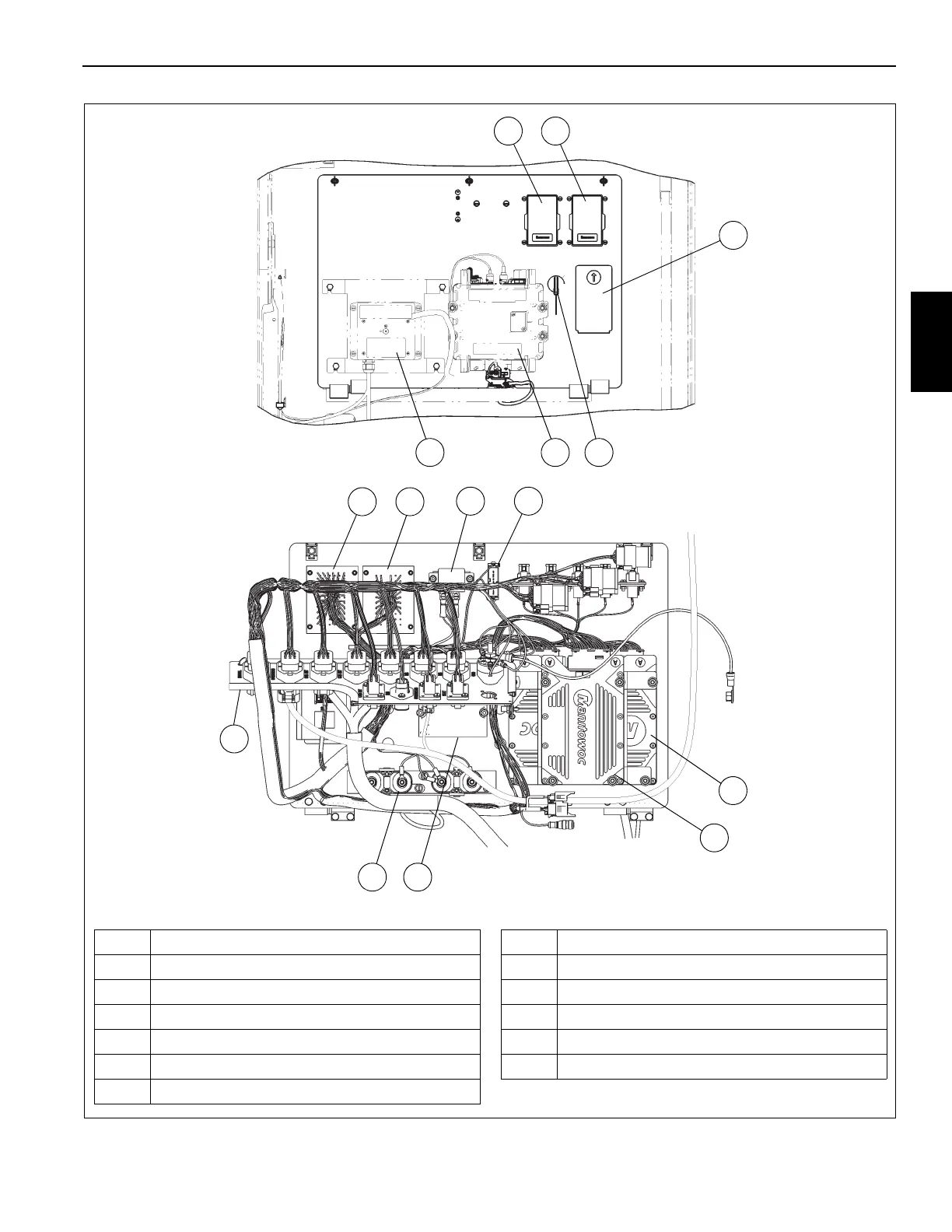
FIGURE 3-2
21
3
6 5
9
10
1 Fuse and Relay Box 2 (see Figure 3-5)
2 Fuse and Relay Box 1 (see Figure 3-4)
3 Diagnostic Connector Box
4 RCL Bypass Key Switch
5 Crane Star Module
6 Wind Speed Module (optional)
7 24V Accessory Relay
8 Battery for MWISCM Module Memory
9 Electronic Control Unit - MWI0L
10 Electronic Control Unit - MWISCM
11 24V to 12V Converter
12 Power Distribution Block
13 Connector Bulkhead Plate (see Figure 3-3)
4
87
2 1
12
13
11
Cab Electrical Panel
Front
Back

 Loading...


