Published 4-20-2015, Control # 502-01 2-59
RT540E SERVICE MANUAL HYDRAULIC SYSTEM
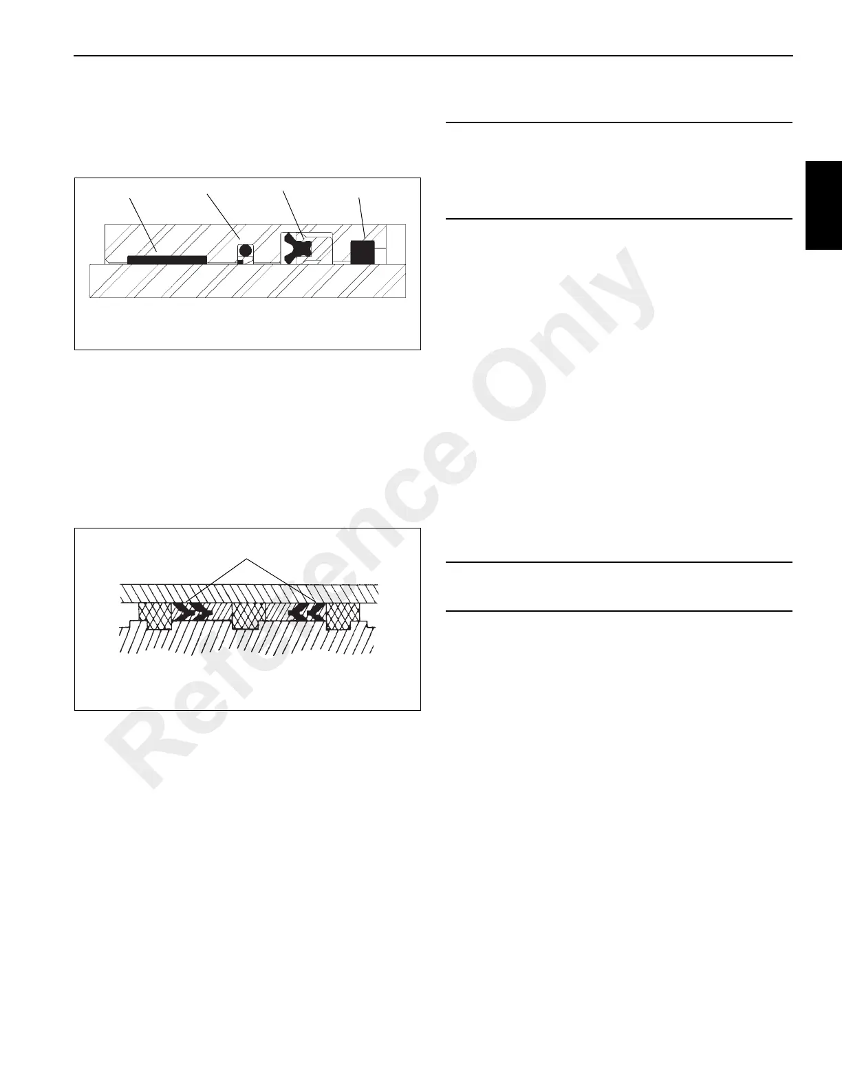
1. Install the replacement wear ring, buffer seal, rod seal,
backup ring and wiper ring in the inside of the head.
Make sure the buffer seal’s step is closer to the rod seal.
Make sure the rod seal’s rim groove is closer to the
buffer seal (Figure 2-29).
2. Install the replacement O-ring and the backup ring on
the outside of the head.
3. Install the replacement O-ring and backup rings in the
inside of the piston.
4. Lubricate the rod with clean hydraulic oil.
5. Slide the head, wiper ring end first, onto the rod.
6. Screw the piston onto the rod tightly. Secure the piston
with the set screw.
7. Install the replacement hydrolock seals on the outside of
the piston. Make sure the “vees” on the two hydrolock
seals point at each other (Figure 2-30).
8. Lubricate all parts freely with clean hydraulic oil.
9. Remove the cover from the barrel. Insert the rod and
attached parts into the barrel with a slight twisting
motion.
10. Install new gasket material to the cylinder head retainer
ring flange as follows.
a. Clean the barrel and retainer ring with Loctite
cleaning solvent 7070 or similar non-chlorinated
solvent.
b. Apply a light coating of Loctite primer N7649 to both
surfaces. Allow primer to dry for one to two minutes.
Primer must be dry. Mating of parts should occur
within five minutes.
c. Apply gasket material Loctite Master Gasket 518 to
one surface. Partial cure is obtained in four hours,
with full cure in 48 hours.
11. Using a spanner wrench or chain wrench, screw the
head into place in the barrel.
12. Install the retainer plate and pin to the barrel. Tack weld
the plate to the barrel.
13. Position the holding valve on the cylinder barrel and
secure with four capscrews and washers. Connect
tubing to holding valve.
14. Pressurize and cycle the cylinder with hydraulic oil
pressure. Test the cylinder at 41,368 kPa/413.6 bar
(6000 psi). Check for proper operation and any leakage.
Make repairs as needed.
Wiper Ring
Rod Seal
Wear Ring
FIGURE 2-29
Buffer Seal
6749
Hydrolock Piston Seals
FIGURE 2-30
CAUTION
Exercise extreme care when handling the rod. Damage to
the rod surface may cause unnecessary maintenance
and expense. Also, take care to avoid damaging grooved
or gland surfaces or rings or seals during rod insertion.
CAUTION
Do not use air pressure to cycle or pressurize the cylinder.
Reference Only
 Loading...


