Published 4-20-2015, Control # 502-01 2-63
RT540E SERVICE MANUAL HYDRAULIC SYSTEM
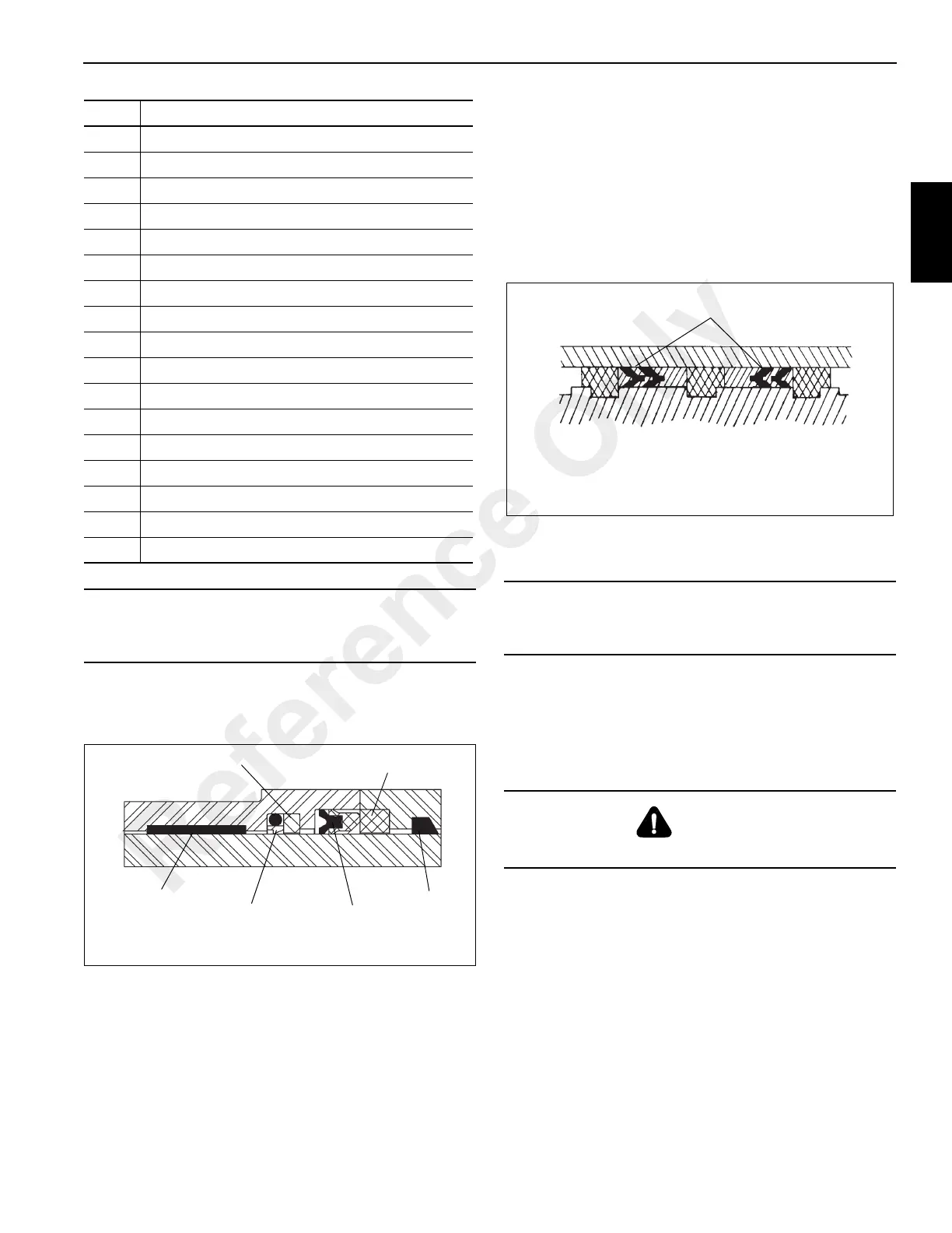
14. Install the buffer seal, backup rings and rod seal into the
head ensuring the seals are assembled properly and
installed in the correct direction (Figure 2-34).
15. Install the O-ring and backup ring onto the outside of the
outer cylinder head.
16. Install the outer cylinder head onto the outer cylinder
rod.
17. Install the spacer onto the rod.
18. Install the O-ring and backup rings into the inside of the
piston and install the piston onto the outer cylinder rod.
Secure the piston in place with the setscrew.
19. Install the hydrolock seals and wear rings onto the piston
(Figure 2-35).
20. Lubricate the outer cylinder rod assembly with clean
hydraulic oil and install the rod assembly into the
cylinder barrel with a slight twisting motion.
21. Using a spanner wrench, secure the outer cylinder head
to the cylinder barrel.
22. Pressurize and cycle the cylinder with hydraulic oil
pressure. Test the cylinder at 32,750 kPa/327.5 bar
(4750 psi). Check for proper operation and any leakage.
19 O-ring
20 Backup Ring
21 Buffer Seal
22 Backup Ring
23 Rod Seal
24 Backup Ring
25 Wiper Ring
26 Head
27 Wear Ring
28 O-ring
29 Backup Ring
30 Seal
31 Seal
32 Backup Ring
33 Wiper Ring
34 Holding Valve
35 Plug
CAUTION
Improper installation of seals could cause faulty cylinder
operation.
Item Description
Wiper Ring
Rod Seal
Buffer Seal
Wear Ring
FIGURE 2-34
6488-1
Backup Ring
Backup Ring
CAUTION
Avoid scratching or damaging the grooved or gland
surfaces or the ring and seals.
DANGER
Do not use air pressure to cycle or pressurize the cylinder.
Hydrolock Piston Seals
FIGURE 2-35
Reference Only
 Loading...


