GROVE Published 10-21-2010, Control# 198-04 4-59
5540F/YB5515 SERVICE MANUAL HYDRAULIC SYSTEM
cylinder has hit bottom. Test to pressure indicated Table
4-7 in both directions as directed in steps 2 through 5.
2. Move the cylinder rod through two complete strokes at
800 psi (5510 kPa) to remove air from the cylinder. Look
for external leaks. If the pressure difference between
cylinder ports is more than 100 psi (689 kPa) during the
second stroke, the cylinder assembly is not acceptable.
Disassemble and inspect for foreign materials or wrong
assembly.
3. Wipe the cylinder rod clean, then move the cylinder
through four complete strokes at 800 psi (5510 kPa), but
do not permit the cylinder to hit bottom on each stroke.
After four strokes, extend the cylinder rod just far
enough to see how much oil has collected during the
four strokes. Inspect the cylinder rod for indication of rod
seal leakage. A thin layer of oil on the cylinder rod is
normal.
4. Fully retract the cylinder rod. Keep the base port open.
Apply test pressure Table 4-7 to the rod port. Hold this
pressure for a minimum of 10 seconds. Visually check
for internal and external leakage. No internal or external
leakage is permitted.
5. Fully extend the cylinder rod. Keep the rod port open.
Apply test pressure Table 4-7 to the base port. Hold this
pressure for a minimum of 10 seconds. Visually check
for internal and external leakage. No internal or external
leakage is permitted.
6. Put plugs in the cylinder ports to keep out dirt during
installation.
Installation
1. Install the cylinder on the machine using the correct
mounting hardware.
2. Connect the hydraulic lines.
3. Lubricate the cylinder grease fittings with recommended
grease.
4. Check hydraulic oil level in the hydraulic oil reservoir.
Add oil if necessary.
5. Start the engine and operate the cylinder(s) through
several complete cycles to remove air. Check for leaks.
Operate cylinders slowly and do not let the cylinders hit
bottom until movement is positive in both directions.
After the circuit is filled with oil, the cylinders can be
operated normally.
6. Check oil level in the hydraulic tank and fill if necessary.
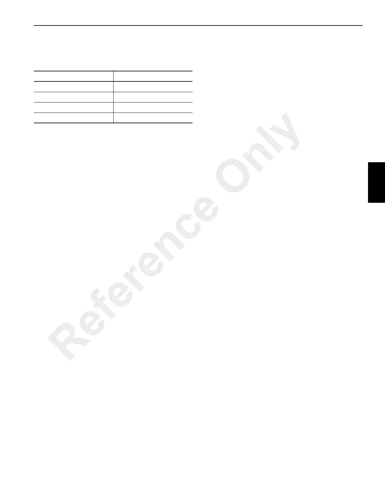
Table 4-7: Cylinder Test Pressures
CYLINDER TEST PRESSURE
Lift 4500 psi (31 005 kPa)
Crowd 4500 psi (31 005 kPa)
Outrigger 4500 psi (31 005 kPa)
Axle Lockout 2500 psi (17 225 kPa)
Reference Only
 Loading...


