• DOK-DIAX02-DDS02.1*ANA-ANW1-EN-E1,44 • 12.96
13
ANALOG interface
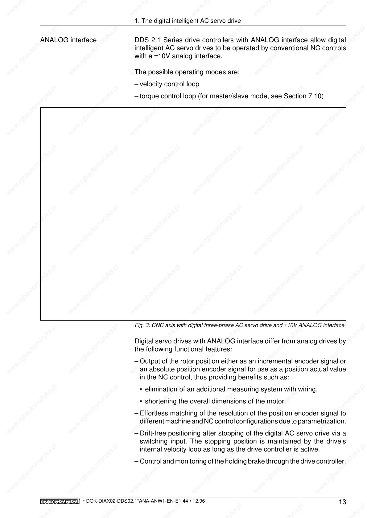
Fig. 3: CNC axis with digital three-phase AC servo drive and
±
10V ANALOG interface
Digital servo drives with ANALOG interface differ from analog drives by
the following functional features:
– Output of the rotor position either as an incremental encoder signal or
an absolute position encoder signal for use as a position actual value
in the NC control, thus providing benefits such as:
• elimination of an additional measuring system with wiring.
• shortening the overall dimensions of the motor.
– Effortless matching of the resolution of the position encoder signal to
different machine and NC control configurations due to parametrization.
– Drift-free positioning after stopping of the digital AC servo drive via a
switching input. The stopping position is maintained by the drive’s
internal velocity loop as long as the drive controller is active.
– Control and monitoring of the holding brake through the drive controller.
Velocity loop
and commutation
PWM-
current
regulation
Current actual value
Digital intelligent drive controller
with analog velocity command interface
Digital
AC servo motor
Velocity
command
Position actual value
U
#
Rotor position
Feedback
+
10V
M
3
~
analog
NC control
(position loop)
K
v
+
W
X
-
SERCOS
09-Nov-89
14.13.04
234554
Zum Mech
Überblick
Modus
ändern
1
1 2 3 4 5 6 7 8
Programm
verlassen
File
service
Antriebs
nummer
Dyn.
ändern
Gruppen
Param
ändern
Ident.-Nr. Text
1 NC-Zykluszeit
2 SERCOS Zykluszeit
3 Sende-Reaktionszeit
5 Meßzeit für Istwerte
6 Sendezeitpunkt Antriebs-Telegramm (T1)
7 Meßzeitpunkt der Istwerte
8 Zeitpunkt für Sollwert-Gültig (T3)
9 Anfangsadresse im MDT
10 Länge des MDT
11 STATUS Zustandsklasse-1
12 STATUS Zustandsklasse-2
13 STATUS Zustandsklasse-3
14 STATUS Zustandsklasse-4
15 Telegrammart
32 Hauptbetriebsart
2000 µ
1000 µ
100 µ
80 µ
100 µ
90 µ
1600 µ
R
R
R
R
R
R
00000000000000000000100000000000
00000000000000000000000000000000
00000000000000000000000000000000
00000000000000000000000000000000
0000000000000101
0000000000000010
1
10
Wert
Antriebsnummer 1
Position
interface
X
RS 232
Parameters
Diagnoses
Operating data
U
#
Position
interface
ENA3A-Abb0.5/InbetrDDS
Drive
micro-
processor
X
d
K
v = loop gain factor
W = command variable
X = control variable
X
d
= W-X
1. The digital intelligent AC servo drive
DDS 2.1 Series drive controllers with ANALOG interface allow digital
intelligent AC servo drives to be operated by conventional NC controls
with a ±10V analog interface.
The possible operating modes are:
– velocity control loop
– torque control loop (for master/slave mode, see Section 7.10)