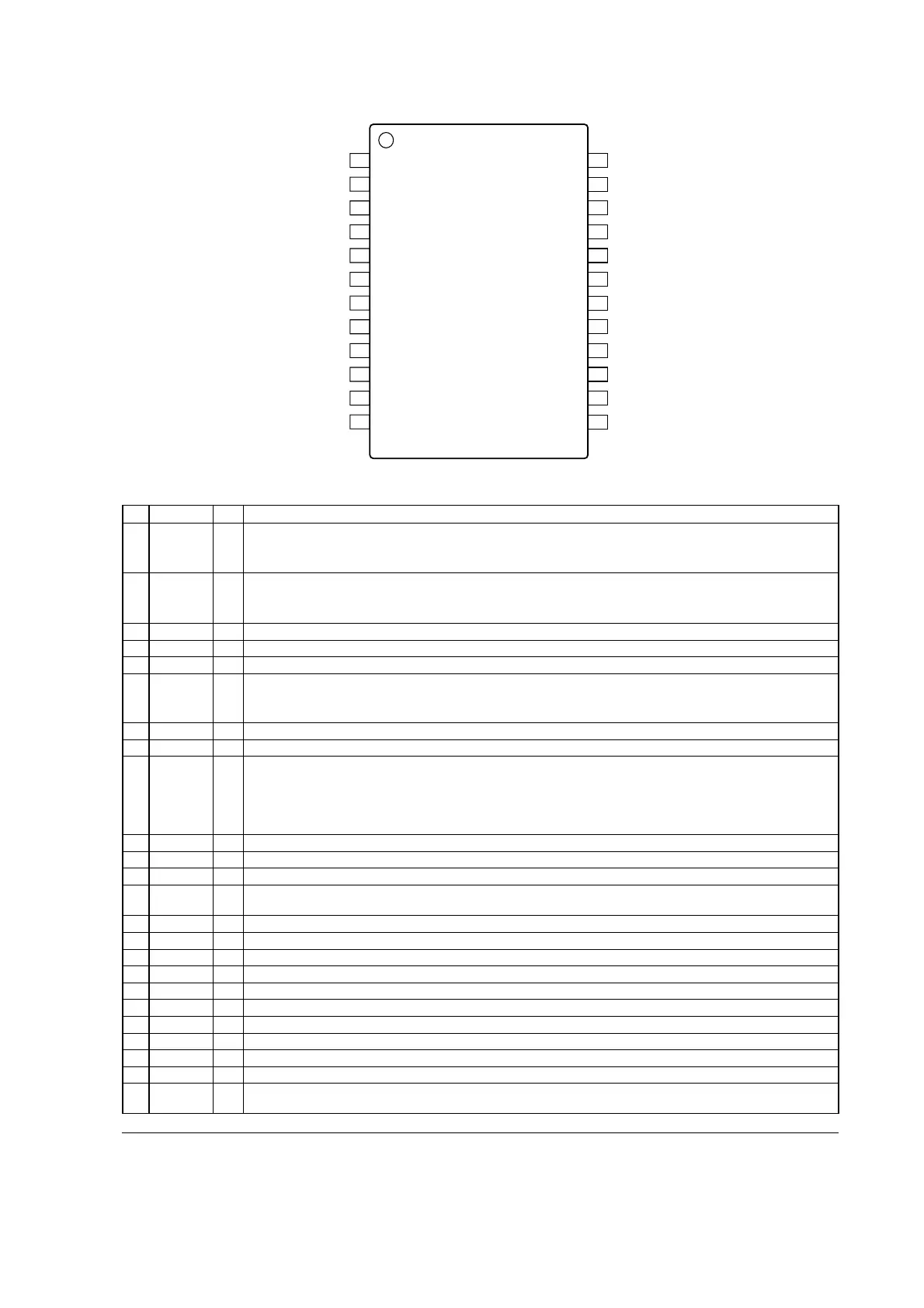
ąTerminal configration
<>24 pin SSOP Top View
SCLK
SDATAO
TE1
DGND
REF
DVSS
AVDD
IN1
IN2
AVSS
1
2
3
4
5
6
7
8
9
10
11
12
SDATAI
CSN
ZCEN2
ZCEN1
OUT1
OUT2
24
23
22
21
20
19
18
17
16
15
14
13
I/ONo. Name Function
1
2
3
4
6
7
8
9
10
11
12
13
14
15
16
17
18
19
20
21
22
23
24
DVSS
TE2
TE3
ZCEN1
ZCEN2
CSN
SDATAI
5
ąTerminal function
I
Minus power supply for digital (-6.0V Typ.)
á
Test terminal (Pull-down) Non connection or connect to DGND terminal.
I
I
Chip select input
I Serial data input
TE2
TE3
REF1A
REF1B
AVSS
AVDD
REF2A
REF2B
DGND Digital ground
á
REF O
SCLK I Serial clock input
SDATAO OD
I
I
Test terminal (Pull-down) Non connection or connect to DGND terminal.
Test terminal (Pull-down) Non connection or connect to DGND terminal.
TE1 I
AI
ȶch2 analog input The output impedance of input signal source is used less than 10k .
IN2
REF2A AI ch2 analog reference voltage input A Connect to ground directly.
REF2B AI ch2 analog reference voltage input B Connect to ground directly.
OUT2 AO ch2 analog output
AVDD Plus power supply for analog (+6.0V Typ.)
á
AVSS Minus power supply for analog (-6.0V Typ.)
á
AVSS Minus power supply for analog (-6.0V Typ.)
á
AVDD Plus power supply for analog (+6.0V Typ.)
á
OUT1 AO ch1 analog output
REF1B AI ch1 analog reference voltage input B Connect to ground directly.
REF1A AI ch1 analog reference voltage input A Connect to ground directly.
AIIN1
Note A: analog terminal, OD: Open drain output terminal, "L" level means V
IL, "H" level means VIH.
Zero-cross control input 1. Select one from four types of zero-cross modes including non-zero-
changes at 1 second or more after the rise of CSN signal.
cross mode. When changing zero-cross modes during operation, set the system so that it
Zero-cross control input 2. Select one from four types of zero-cross modes including non-zero-
changes at 1 second or more after the rise of CSN signal.
cross mode. When changing zero-cross modes during operation, set the system so that it
Reference voltage output for digital For attaining stabilization, connect this terminal to
DVSS terminal through a capacitance of 10μF or higher (C
REF).
And please do not use this terminal output for the drive purpose of an external circuit.
Serial data output
Serial data are outputted from this terminal when CSN pin is "L" level. This terminal becomes
high-impedance state when CSN pin is "H". Since it is an open drain output pin, pull it up
connected. Do not allow output current of 1.5mA or over.
through a resistor to the power supply voltage (to be AVDD or less) of a device to be
When avoid the use of this terminal, connect to ground.
ȶch1 analog input The output impedance of input signal source is used less than 10k .
When avoid the use of this terminal, connect to ground.