Instruction Manual
20
– Instruction Manual
5.3
Connector Description
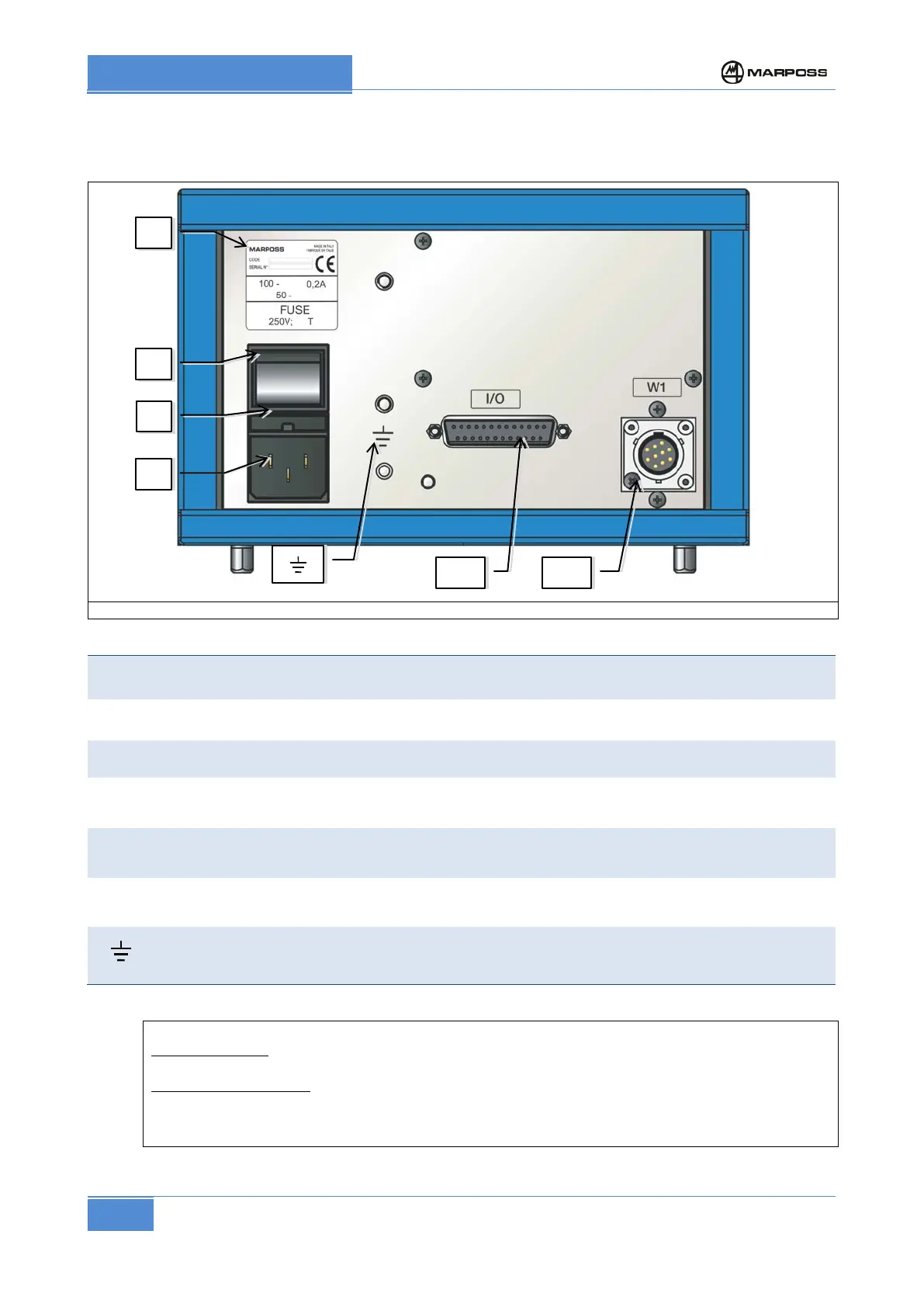
Figure 2. Connections of the electronic unit (rear view)
A
Identification plate (code and serial number) of the electronic amplifier and power supply
specifications (power supply voltage value, phase rating). (See section 6.3.1 )
B
Power-on switch
C
Fuse on supply voltage.
D
Electrical power supply collector. See para. 6.3.1 “Connecting the power supply”
I/O
Male, 25 pin DSUB type connector for machine logic interface I/O signals. See section 6.4.
W1
10-
pole male connector. Connection of measuring head. If the measuring head has two
transducers and two connectors, the special Y-shaped connection cable is used.
M5 terminal for “operational earth” connection.
P1 WITH CASE: Position the unit so that it is not difficult to disconnect the two connectors
manually (“D” and “I/O” in Figure 2)
PANEL MOUNTED P1
: Must be fitted with a switching device that can be used to isolate the unit
from its two power supplies (“D” and “I/O” in Figure 2).
The switching device must isolate all the power supply conductors and be easy to access and
operate. It must not be necessary to use any kind of tool to operate it.