Instruction Manual
Instruction Manual
27
6.3
Connections of Electronic Unit
6.3.1
Connection to supply voltage
P1 is provided with automatic change of voltage that allows a connection to supply voltage according to the
following specifications:
100÷230 V a.c. r. m. s. ±10%
Max. current consumption: 0.2 A.
The unit is fitted with a non resettable fuse (see Figure 2 ref. C) that protects it against any faults caused by
the internal components.
Fuse specifications: 1A 250V 5x20 slow-blow HB.
Always use components having the same specifications when replacing the fuse.
Install a “B” o “C” curve (see Standard EN60947) circuit breaker type protection device with a
current rating not exceeding 1 A, or equivalent fuse. The power supply should also be fitted with
a differential circuit breaker.
In the event of a momentary power failure the machine outputs ( see para.6.4) may change
state. Take the necessary measures to avoid harming personnel or property.
6.3.2
Functional Earth Connection
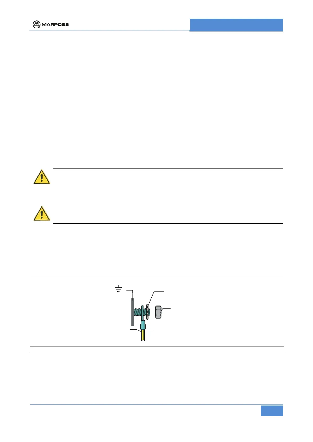
Connect the unit to earth using the earth stud. To earth the unit, connect the stud to the centre of mass on
the machine tool where it is installed, using yellow/green cable with a minimum cross section of 4 mm sq,
ensuring that the connection is as short as possible
Fit a serrated washer (see Figure 8 Functional earth connection ) to ensure that the contact remains good.
Figure 8 Functional earth connection
In the case of the panel mounted version, secure the P1 to a metal panel on the machine that is connected
to the centre of mass of the machine (which is, in turn, connected to earth), using the pins present on the
rear of the P1 front panel. Check that there is a good ohmic connection between the machine metal panel
and the P1 panel.
Terminal
Yellow/green cable
Section 4 mm
Cable
terminal