© 2023 Maxeon Solar Technologies, Ltd. All rights reserved. | 549549 Revision A - October 2023
Specications included in this document are subject to change without notice
31
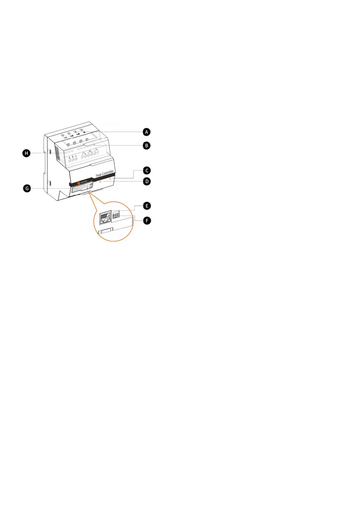
10.3. Description
A. Power supply terminals
For three phase grids, L1 connects to the rst phase,
L2 connects to the second phase, L3 connects to the
third phase and N connects to the Neutral cable.
For single phase grids, L1 connects to the rst phase
and N connects to the Neutral cable.
B. Current sensor terminals
For three phase grids, I1-, I1+, I2-, I2+, I3+ and I3-
connect to the black and red wires of each current
sensor.
For single phase grids, I1-, I1+ connect to the black
and red wire of the current sensor.
C. Communication mode indicator
Green constant: Communicating with EV charger via
Modbus TCP (Modbus over an Ethernet cable).
Off: No communication established.
D. System status indicator
Green: Module is powered and monitoring.
Red: Fault (refer to Troubleshooting section in the
Peak Controller installation manual provided).
E. Ethernet Port
For Communicating with the charging station via
Ethernet.
F. Maximum current limiter
Limits the maximum current for the SunPower Drive
charging station by setting the position of 3 DIP
switches (refer the Peak Controller installation manual
provided).
 Loading...