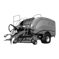
McHale V Series Baler
55
Some of the more inaccessible areas are fed from centralised blocks, on either side of
the machine, via flex pipes. The rest are individual, but the two lower tension arm rollers
require a special procedure to align them with access slots in the chamber walls.
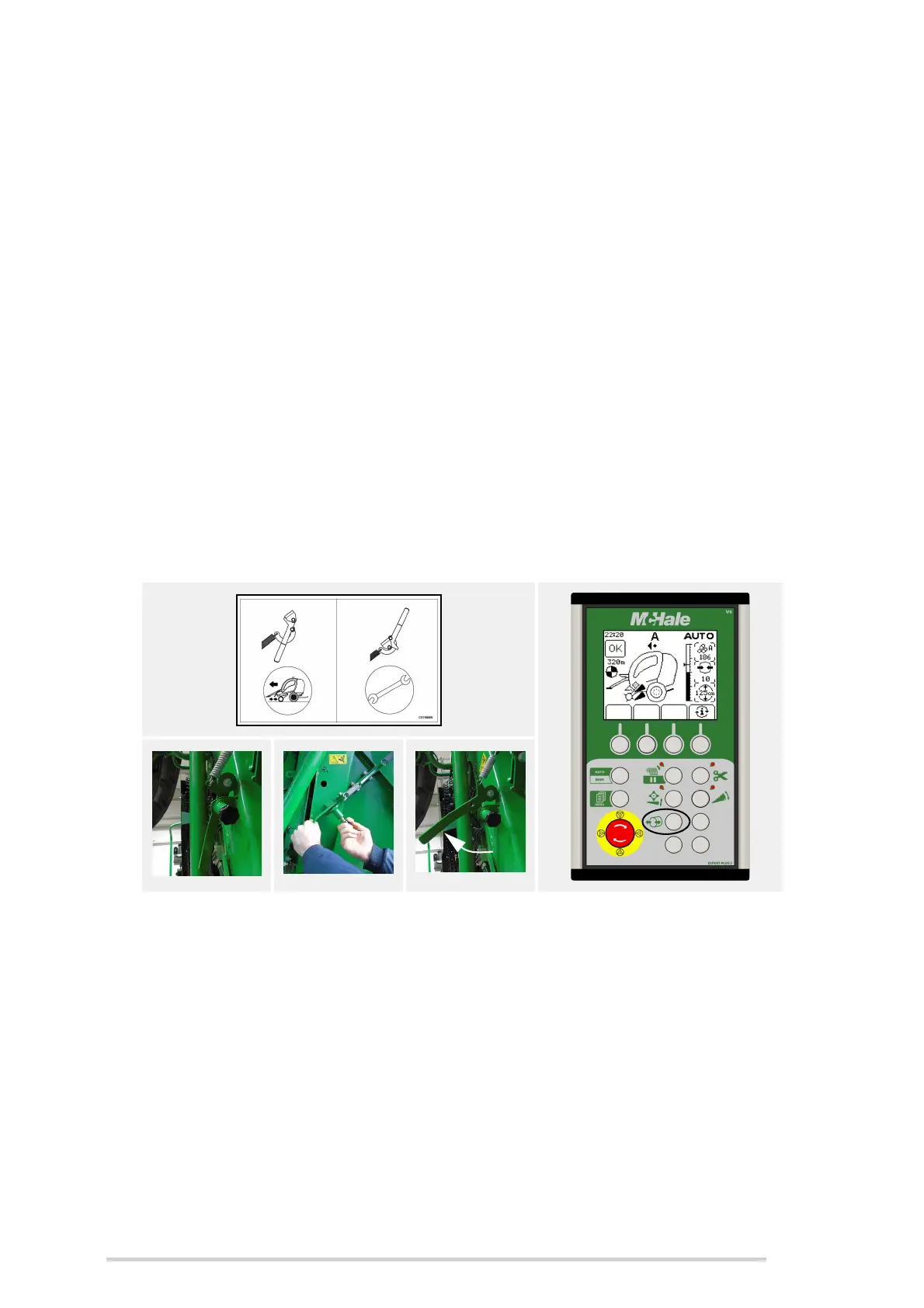
Operate the tension arm lock (B) using the following procedure. (See ‘Tension arm
lock’)
1. Move the lock lever (B) from the normal working position to the maintenance
position, this will cause the stop to move into the bale chamber.
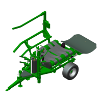
2. Next the tailgate of the machine should be opened fully so that the tension arm
passes the stop.
3. In order to release the pressure from the belts the tailgate must now be closed
fully. This ensures that the tension arm rests on the stop inside the bale
chamber, allowing the belts to hang loose.
4. Close the chamber door lock immediately. (See ‘Chamber door lock’)
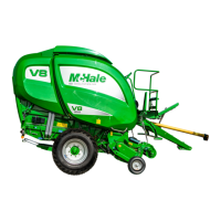
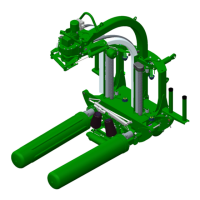
Release the hydraulic pressure from the tension arm by pressing ‘density release’
(button 9) on the control box until the pressure on the clock falls to zero.
The hydraulic and spring pressure is now released allowing the operator to access the
grease points through slots in the chamber walls, two on either side.
To release the tension arm lock, once tension arm rollers have been greased, the lock
lever (B) should be returned to the working position, before opening the tailgate fully to
release the stop and then closing the chamber again. The belts are now re-tensioned
and the machine can resume as normal.
6.3.5 Oil pump adjustment
The oil pump is factory pre-set and under normal circumstances should not require any
adjustment. If insufficient oil delivery is noticed on a particular chain, then the pump can
be adjusted as follows:
The delivery is regulated for pairs of pressure connections, one above the other. Firstly
unscrew the black plastic cover on top of the pump, which exposes the five adjusting