Insta lling a Plug-on Digicom
1. A dig icom type DC54 or DC58 ca n be fitted in the base of the TS 700 main panel. The unit
should b e fitted in accordance with the installation instruction s supplied with it and
connected to JP3.
2. The alarm chan nels for the plug-on d igicom are programmed as required (page 16). It will
be necessary to fit a programmed NVM in t he digicom or to program it in accordance with
the instructions supplied with the unit.
Insta lling a stand-alone Digicom or RedCARE
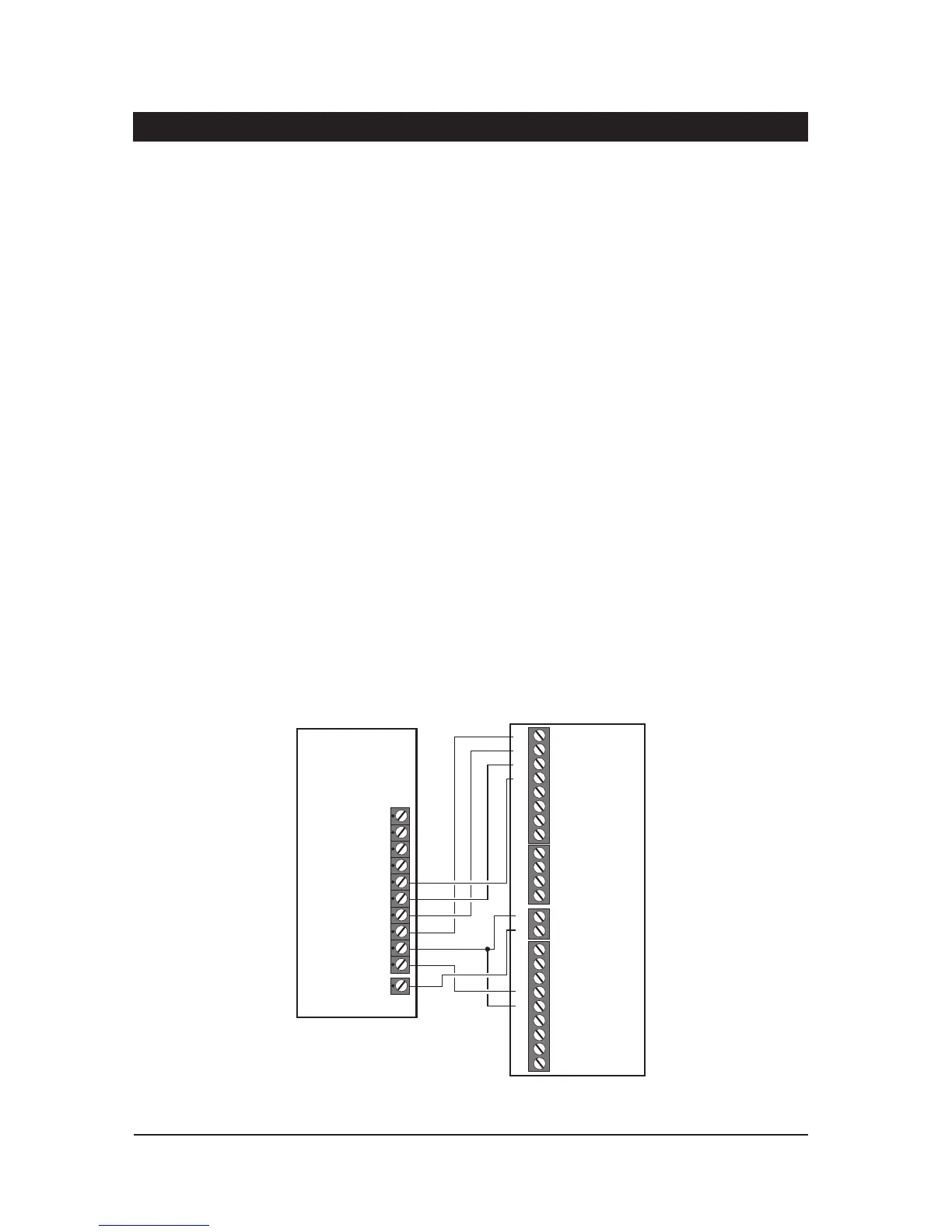
A stand-alone digital communicator, Red CARE STU or Paknet i nterface card can be connected
tothesystemtotransferpanelalarmstatusin format iontoad edicatedalarm receivingcentre.The
control panel has the following connections (Figure 6) for a digicom etc.
1 to 8 - These are the programmable digic om outputs. They are normally at +12V
and switch to 0V when active.
+DC POWER - This provides a permanent +12 V powe r to the digi com. The ou tput is
un-fused a nd therefore should only be used if the digicom is fitted inside
the control pan el.
LINE FLT - W hen thi s input is switch ed to +12V a telephone l ine fault condition will be
gen erated.
REM RE SET - If the system is programmed for“EngineerReset”,then afte r a full alarm the
system will require resetting, normally this is done by the engineer orcoded
rem ote reset. A pplying a -ve to this input terminal will cause the system to
reset after a full alarm . This input could be connected to t he “Control”
output on a RedCARE STU so that t he Alarm Receiving Centre ca n poll the
STU and thus reset the p anel.
10
System Installation TS700 Installation Manual
Control
Pan el
3GSTU
1
1
+DC POWER
Program
As:-
Open (08)
Alarm (05)
PA (06)
Fire (07)
LINE FLT
AUX 0V
2
2
3
3
4
4
5
TB1
Channel Inputs are
Programmed as
Positive Removed
TB2
TB3
TB4
Control
Line
Fault RPS
5
6
6
7
7
0V
NO NO NONC NC NC
8
8
C CC
A+ A+ A+ A+ V+
Figure 6. 3G STU RedCARE Connections