Insta lling Remote Keyp ads and LECs
The following type s of devices may be connected to the cont rol panel:
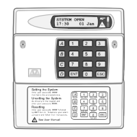
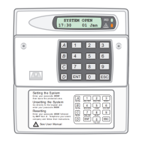
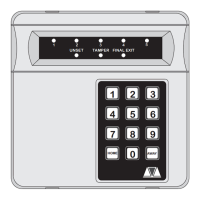
NETLED - 4 x 7 Se gment LED display.
NETSTAR - 8 Character Starburst LCD display .
NETARM - Remote Arming stat ion (Pow er LED & programmable "Function " LED).
TS700.LE C - 2 zone local exp ansion card.
Any combination of devices can be used on the same system, pr oviding the total number does
not exc eed four.
1. Al waysensurethatallpower(mainsandbattery)is removedbeforemakin g anyconnections
to the remote keyp ad.
2. Separate the cover and base by using a screwdriver t o push 2 of the clips (top or bott om)
inward from the base indents, then lift the cover assemb ly, noting that the PCB is fixed to the
under side of the cover.
3. Hold thebase inposit ion (keyhole to the top)and markthethree s ecur ing hol es, drilland plug
the wall as required. Pass all the cables into the base via the cable entry points as
appro priat e and secure the base to the wall.
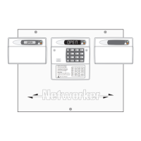
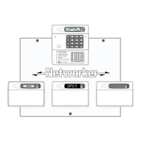
4. Connect “Remote Network” and detection circuit cables to the appropriate terminals, see
Figure 4.
5. Set the I/D sele ctor jumper link to the requ ired position:
I/D Selector Circuit A Circuit B Panel Ou tput
1 09 10 5
2 11 12 6
3 13 14 7
4 15 16 8
ENG / NULL N/A N/A N/A
☞
No two remote keypads or LECs should have the same I/D.
☞
If the I/D is set to “ENG” the remote key pad will function as an Engineer’s ke ypad
allowing it to be plugged onto the co ntrol panel so that system programming an d
testing may be carried out (see Engineer’s Keypad).
6. For details on all remote key pad option li nks, please refer to the instructions supplied with the
rem ote keypad.
7. Finally clip the rem ote keypad cover onto the base being careful not totrap anycables or to
obstruct the t amper switch.
Engineer's Keypad
Normally a ll system progra mming will be c arried out fr om one of the install ed remote ke ypads.
However sometimes it may be more convenient to program th e system at the co ntrol p anel, t his
can be achieve d by using an Engineers Keypad. This is temporarily plugged on to the control
panel (JP2). To convert a standard remote keypa d to a n "Engineers Keypad" an in terface le ad
can be obtained from your supplier (P/No. NETEKI).
8
System Installation TS700 Installation Manual