Detection Circuits and Attribute s
Detec tion circu its 1 to 8 for the panel and 9 to 16 for the remote keypads/ LECs are programmed
as follows:
1. Ensure that "Engineer M enu 1" is selected.
2. Press 4 to select the Circuits and At tributes option.
3. Select circuit number (01 - 16) and press [. The curren t ci rcuit
type wil l be displayed.
4. Enter the new circuit type, using keys 0 to 9, or A, B or C (Table 3).
Press [ to accept.
5. The circuit number, type and attributes a re displayed in turn.
6. Select new attributes by using keys 1 to 5 (T able 4) these will
"toggle" the attributes on & off. Press [ to accept.
7. Continue for r emaining circuits with steps 3 to 5.
Key Display Circuit Type
0
NoTU
Not Used - A circuits that is not monitored.
1
NITE
Ni ght - A circuit that will generate a full alar m when the system is set.
2
24HR
24 Hour - A ci rcuit which is monitored at all ti mes. When activated in the unset condition a
loca lal arm isgenerated andw hen activated inthesetconditionafullalarm isgenerated.
3
PA S
PA Silent - Acircuitwhich ismonitored atalltimes.When activateditwillsignal a P.A. onthe
Digicom outputs and activate any oth er outputs that have b een prog rammed as P .A.
4
PA A
PA Audib le - A circuit which is monitored at all times. When acti vated it will signal a P.A. on
the digicom outpu ts, activate any other outputs that have been programmed as P.A. and
generate a full alarm condition.
5
FIRE
Fire - A circuit that is normally connec ted t o a smoke or heat detector. When activated it
wi ll generate a fire tone on internal sounders and the external sounders are pulsed.
6
Au
Auxiliary - A circ uit which is monitored at all times. When activated it will cause any of the
outputs that have been prog rammed as ` Auxiliary' to go active.
7
FE
Final Exit - This must be the last detector or door contact that is activated when leaving or
ente ring the pro tected area. When the setting mode for the area is programmed for "Final
Exit" setting, opening and closing of this circuit during the exit procedure will cause the
system o r area to set. Once set, activation of this circuit will start the entry timer.
8
ET
Exit Terminator - A circuit that is normally connected to a push button outside the
pr otected area, which operates as foll ows:
a) Whenthe settingmod e isprogrammed as"Timed Exit",activationof thiscircuitwillcause
any remain ing exit time to be truncated to zero.
b) When the setting mode is programmed as "Exit Terminator", the area will set when the
Final Exit circuit has been operated and the exit terminator button is pressed.
9
FULL
FullSet Key switch - A circuitwhich can be conn ected to a keyswitch toallow thesystem to
be full-set (active) and unset (healthy).
A
PSA
Part- Set A Keyswitch - A circui t which ca n be connected to a keyswitch to allow part-set
gr oup A to be set (active) a nd unset (healthy).
B
PSB
Part- Set B Keysw itch - A circuit which can be connected to a keyswitch to allow part-set
gr oup B to be set (activ e) and u nset (healthy).
C
PSC
Part- Set C Keyswitch - A circuit which can be connected to a key switch to allow part-set
gr oup C to be set (active) and unset (healthy).
Tabl e 3. Circuit Types
18
Pr ogramming TS700 Instal lation Manual
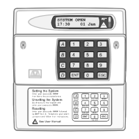
CT.--
En ter cir cui t number 01 - 16.
NITE
En ter new circuit type 0 - 9 or A,
B or C (s ee Ta ble 3.)
Acc
Press 0 - 5 to `toggl e' circuit
attributes on & off (see Table 4.)