System Installation
Cable Routing
When installing cables ensure that detection, remote keypad, bell and mains cables are kept
separated from each other and that panel internal wiring is clear of the main PCB.
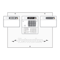
Installing The Control Panel
Proceed as follows:
1. Open the controlpanel by removing two screwsfrom the frontcover. Rem ove the cover by
sliding it up slightly to disengage the bottom clip, disconnectthe earth bonding cable from
the spade connection on the front cover, then lift clear.
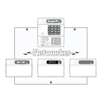
2. Note the position of the cable entries as follows:
(a) Ten 20mm cable entries and for detection, alarm and remote keypad cables.
(b) A 20mm cable entry for m ains (240V) below the mains input terminal block.
☞
The mains cable must enter the control panel through its own cable entry and m ust
not be mixed with other cables.
3. Hold the control panel back box in the required position (keyhole to the top) and mark the
centre of the keyhole position. Remove the back box, drill and plug the hole.
4. Screw a No 10 screw into the plugged hole. Re-position the back box and mark the
remaining four securing holes. Rem ove the back box, drill and plug the holes.
5. Re-position the back box and secure using not less than 30mm x No 10 screws through the
four dished 5m m holes.
6. Passallcablesintothebaseviathetrunkingholesorknockouts,gromm etingasappropriate.
7. If required install and connect the following:-
(a) Stand alone digicom or RedCARE STU.
(b) Plug-on digicom type DC54, or DC58.
(c) Output modules type CPA6.OM.
(d) Printer type DATAC or serial RS232 via a printer adapter (MPA/DCI).
Mains Connections
Themainssupplyisconnectedtoa3wayterminalblockconnectoronthemainPCB.Allelectrical
connectionsm ustbecarriedoutbyaqualifiedpersonandcomplywiththecurrentIEEregulations.
+
Tocomplyw ithEuropeanregulationsthesupplyshouldbefedfromareadilyaccessible
disconnect device, e. g. un-switched fused spur fitted.
+
When making mains connections it should be ensured that if the cable slips in such a
wayastoplaceastrainontheconductors,theprotectiveearthingconductorwillbethe
last to take the strain.
5
TS700 Installation Manual System Installation