Pre Power-Up Check s
O nce the syst em is in stalled, but prior to pow eri ng-up give the syste m one final check to ensure
that:
1. Thewiringconformsto the requirements deta iled in this manual and thatal l interconnections
are correct (A to A, B to B etc.).
2. Al l s ystem cables are keptcl earofmains sup ply cables, telephone cablesand R .F. cables.It
is recommended that cable ties be used to keep cables separated.
3. Verify that maximum cable lengths and resistances are not exceeded.
4. Mains power supply cables to the system are connected to a n un-switched fused spur .
5. G rommets are used where cables enter metal housings to ensure that i nsulation is no t
comp romised.
Initial Power-Up
To power the system for the first time:
1. Place a small screwdriver bla de between the pins on the control pan el PCB, marked
"FACTORY RESET". Thi s will ensure the factory default parameters are set (see Table 1).
2. Switch on the 240V mains supply and remove screwdriver blade.
3. Check that power LED on the control panel PCB is illuminated.
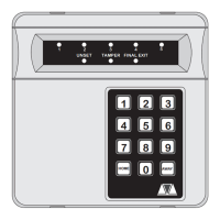
4. Check tha t the remote keypads display "LT" ( Panel Lid tamper). The remote keypa d
sounders and extension loudspe ak ers will operat e.
5. Enter the engineers passcode (default 1234) to s ilence the sounders.
6. Connect the standby battery.
Power-Up Checks
W hen the initial power-up checks h ave been complete d, chec k the following:
1. Using avoltmetermeasuretheDCvoltage ateachremotekeypadandensurethevoltageis
greater than 11V whil st runnin g on the system standby battery.
2. Using a voltmetermeasure theDC voltage betweenmainsearth and +12V,andthe voltage
between mains earth and 0V. In both cases t he me as urement should b e 1V o r less. If the
Voltage is great er than 1V,the system has an "Earth Fault" and all cables should be checked
for isolation to earth.
3. Using a voltmeter set to a low DC voltage range, measure the voltage across the control
panelPCBtestpo int(V).Tocalculatethesystemcurrentconsumption multiplythereading by
ten, e.g., a reading of 70mV = 700mA. Ensure that the r eading is not greater than 1.0A.
4. Rep eat test (3) with the system in an alarm condition and ensure t hat the reading is not
greater than 1.0A .
5. The system is now ready to be programmed see "Programm ing".
14
System Installation TS700 Installation Manual