IGNITION
Page 2A-10 90-828631R3 MARCH 1999
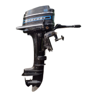
Flywheel Assembly
The flywheel assembly contains one permanently charged magnet which is bonded and
retained to the inner wall of the flywheel. This magnet is segmented with 3 positive and 3
negative poles. (12 pole) (6 positive pulses per revolution).
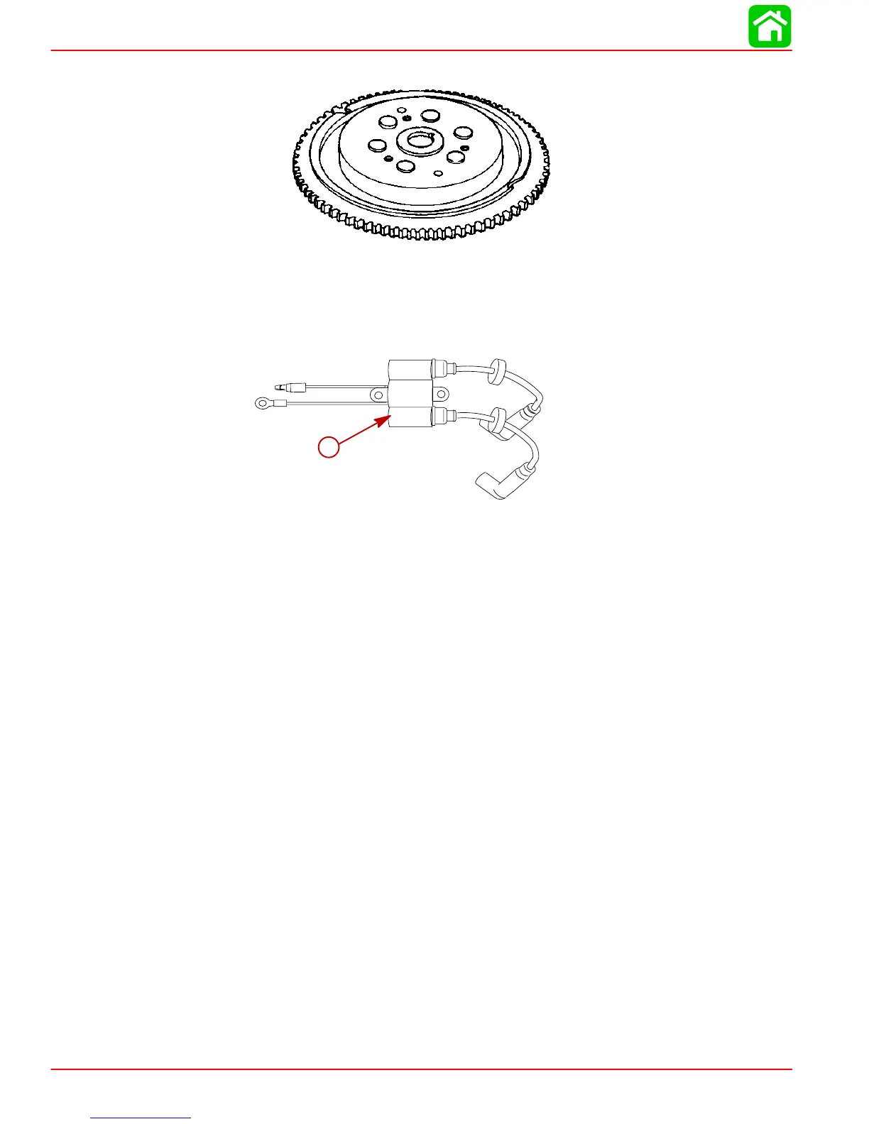
Ignition Coil
a
a-Ignition Coil and High Tension Lead Assembly
The primary (+) side of the ignition coil receives voltage discharged from a capacitor in the
ignition (CDI) unit. The voltage is multiplied by the coil until it can jump the spark plug gap.
The ignition coil will produce a high voltage current each crankshaft revolution, producing
a spark at each cylinder at the same time (Waisted Spark Ignition). Ignition coil maximum
output is approximately 40,000 volts.

 Loading...