5-4 | Model 933 UV Analyzer
Analog Output Calibration
Current Calibration
The current outputs are calibrated at the factory. If a current output mod-
ule is replaced or added, calibrate that output (from the Output Setup
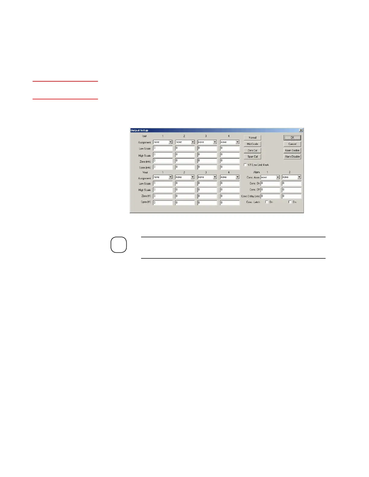
dialog box). Calibration of a current output is performed by entering the
measured low-scale (Zero) and full-scale (Span) signals for each output
(Figure 5-4). These values are used to offset the output to the correct val-
ues.
When performing current or voltage calibration, do not enable (check)
V/I Low Limit 4 mA until after calibration is complete.
To calibrate the current outputs:
1. Measure the Zero (low-scale) signal of each output:
a. Click Zero Cal to change its status to On. The status of Normal, Mid-
Scale, and Span Cal should be Off.
b. Connect a current meter to Pins 1 and 2 (at J109 on the Customer
I/O board) and measure the current of Output 1. Under Current
Outputs, enter the value next to Zero (mA), under the first column
(Output 1). Place a 250 Ohm resistor in series of the multi-meter for
accurate calibration.
Repeat this step for Output 2 (Pins 3 and 4), Output 3 (Pins 5 and 6),
and Output 4 (Pins 7 and 8), recording the value for each output in
the corresponding field.
NOTE
Figure 5-4.
Output Setup dialog
box.
Setup (tab)Output
 Loading...