87
Common Usage:
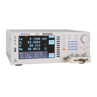
1. Trigger Signal: Uses the normal open switch of the relay to control the machine to
perform tests. (Note: The trigger signal must last over 5mS.)
Figure 3-8-4 Illustration of Recommended Connection for the Trigger Signal
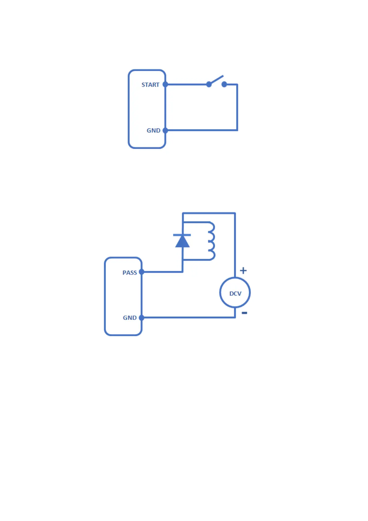
2. Output Signal: Uses the output signal to control the relay. For safer usage, please
connect a Zener diode to the relay coil. (Voltage used must be less than DC 24V.)
Figure 3-8-5 Illustration of Recommended Connection for the Output Signal