86
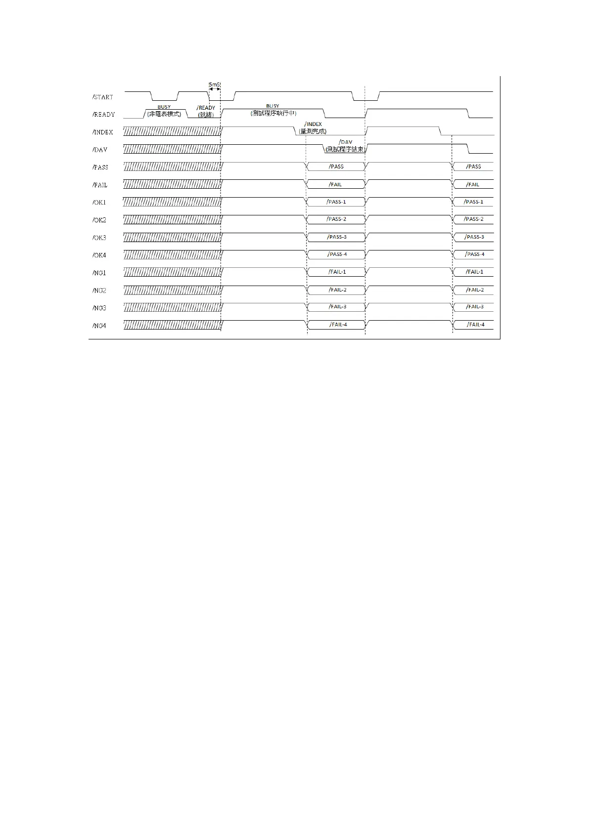
Handler I/O Timing Diagram:
Figure 3-8-3 Handler I/O Timing Diagram
※ Note: The Handler Interface is only applicable under Meter Mode and Multi-Step Test Mode.
When test is triggered under Meter Mode, the Meter Mode will be automatically be
set as Single Mode.
Instructions:
All output pins have open collector output and no voltage or signals are output. The current that
passes each contact must not exceed 30mA and the voltage must not exceed DC 24V.