Technical Information
11
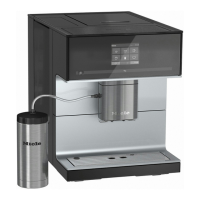
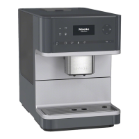
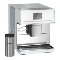
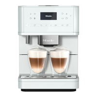
CM6
2 CM 63x0
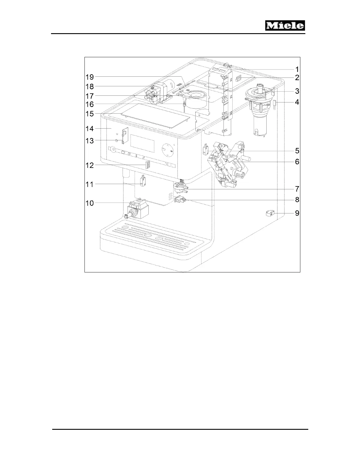
Figure D-2: CM 63x0 Component Layout
1
EPL power electronic (1N1-1, 2N1-1)
11
Drip tray present switch (S87-1)
2
Chute present switch (S87-5)
12
Spout present switch (S87-6)
3
Grinder (M25)
13
Water tank sensor (B3-18)
4
Grinder thermostat (F3-3) 90°C
14
EPB display/control electronic (N1-2)
5
Brew unit present switch (S87-2)
15
Cup warmer (R39)
6
Brew unit drive (M26) with
16
Heater NTC (R30-14)
2 position switches (S60-1, S60-2) and
17
Heater (R1)
grind amount step contact switch (S51-4)
18
Ceramic valve (M29) with
7
Flow meter (B3-4)
position switch (S60-3) and
8
On/off switch (S2)
step contact switch (S51-1)
9
Door contact switch (S24)
19
2 heater fuses (1F8, 2F8) 192°C
10
Pump (M7) with thermostat (F3-2) 105°C