Technical Information
44
CM6
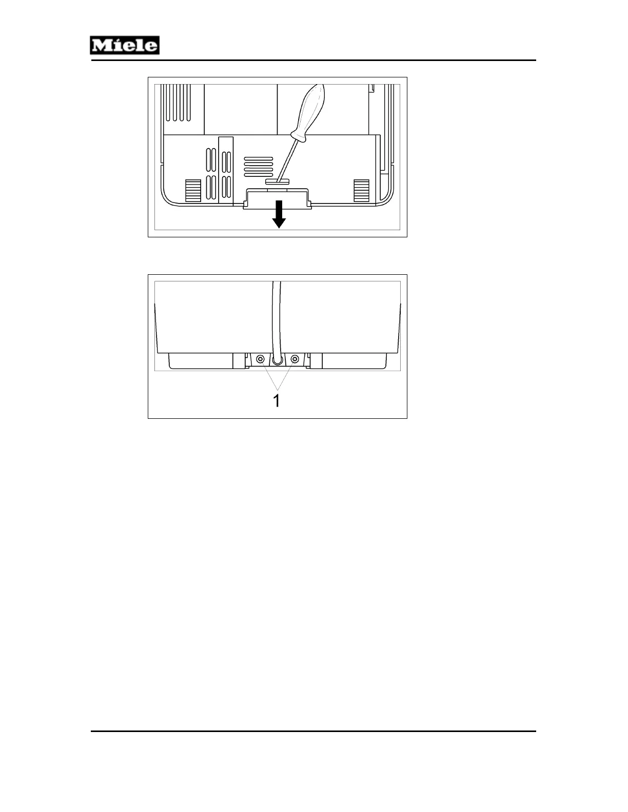
Figure 001-26: Screw Cover
4. Remove the 2 T10 screws (Figure 001-27, Item 1).
Figure 001-27: Side Casing Screws at Rear of Appliance
5. Press on the side panels and slide them back to release the locking tabs.
6. Disconnect the hose from the water tank side panel.
4.7 Cup Warmer (R39) Removal (CM 63x0 Only)
1. Remove the top cover; see Section 001-4.5.
2. Remove the 4 T20 screws securing the cup warmer to the underside of the top
cover (Figure 001-28, Item 1).