Technical Information
60
CM6
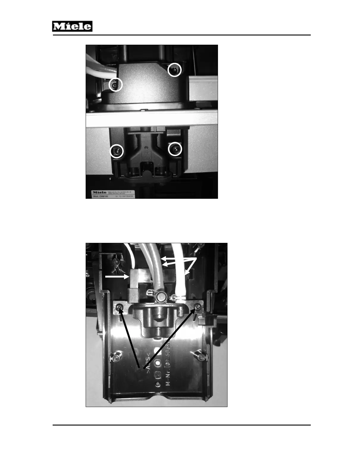
Figure 001-51: Hose Cover Screws
7. Disconnect the three hoses (Figure 001-52, Item 1) and release the spout present
switch (Figure 001-52, Item 2) from the dispenser assembly.
8. Remove the two T10 screws securing the dispenser assembly to the dispenser
housing (Figure 001-52, Item 3) and separate the assembly from the housing.
Figure 001-52: Dispenser Assembly Hoses and Screws; Spout Present Switch
2
1
3