Technical Information
16
CM6
10
Coffee/milk spout
12
Drip tray
2.3 Brew Unit Drive
2.3.1 Microswitch Locations
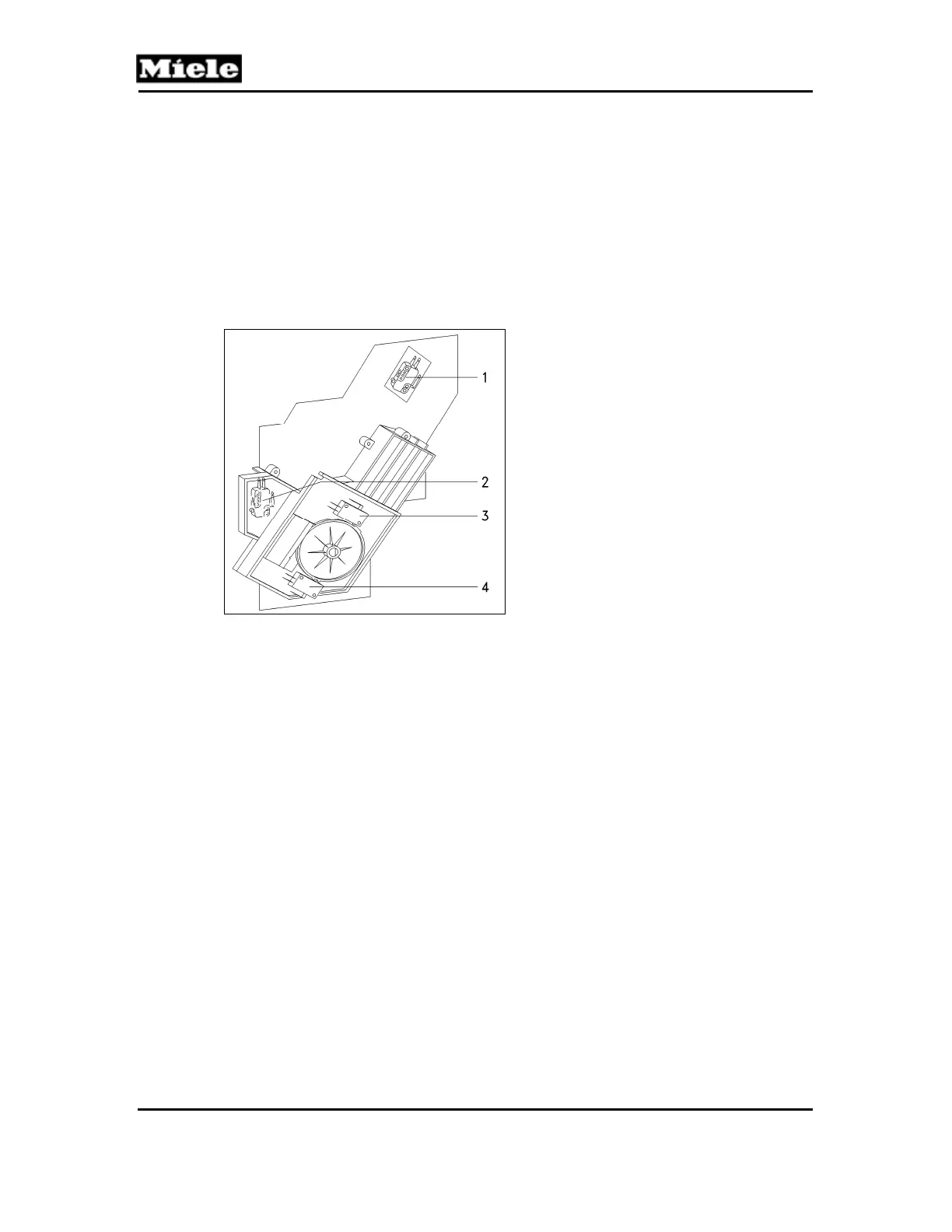
The brew unit is controlled via 4 microswitches (Figure 001-8).
After the brew unit has been activated, if one of the two positioning microswitches
(Figure 001-8, Item 3 or 4) has not switched within approximately 10 seconds, the
following fault is indicated: F73 – Brew Unit Fault (Section 001-3.10).
Figure 001-8: Brew Unit Drive Switches
2.3.2 Brew Unit Presence Monitoring
When the brew unit is correctly installed (i.e. inserted and locked into place), the brew
unit present monitoring microswitch is activated (Figure 001-8, Pos. 2).
2.3.3 Electronic Grind Amount Compensation
The grind amount compensation evens out variations in grinder settings and coffee
types.
The grind amount can be set in the customer programming mode for the various coffee
types, and corresponds to a specific grind time; see Table 001-2.
During the brewing process, the actuator on the brew unit drive passes over the pin on
the microswitch; see Figure 001-9. The further the actuator advances, the greater the
ground quantity in the brew unit.
1 Grind amount compensation microswitch (S51-4)
2 Brew unit present monitoring microswitch (S87-2)
3 Top positioning microswitch (“home” setting) (S60-1)
4 Bottom positioning microswitch (“brew” setting) (S60-2)