Technical Information
3
CM6
3.16 F235 - Display/Control Electronic (N1-2) Communication Fault ................... 29
3.17 “50 Portions until Descale” Message ............................................................ 29
3.18 “Empty Drip Tray” Message, But Drip Tray Isn't Full ..................................... 29
3.19 Drip Tray Must Be Emptied Frequently ......................................................... 29
3.20 Coffee or Espresso Too Cold ....................................................................... 30
3.21 Milk Froth Unsatisfactory or Sputtering ......................................................... 30
3.22 No or Very Little Coffee Flowing from Spout ................................................. 30
3.23 Coffee Tastes Too Bitter ............................................................................... 30
3.24 Coffee Grounds Next to the Brew Unit ......................................................... 31
3.25 Water Pump Does Not Pump ....................................................................... 32
4 Service ................................................................................................................ 32
4.1 Drink Settings (Customer Programming) ...................................................... 32
4.2 Machine Settings (Customer Programming) ................................................. 33
4.3 Service Programming ................................................................................... 37
4.4 Service Mode ................................................................................................ 38
4.5 Top Cover Removal ...................................................................................... 41
4.6 Side Casing Removal ................................................................................... 43
4.7 Cup Warmer (R39) Removal (CM 63x0 Only) .............................................. 44
4.8 Front Panel Removal .................................................................................... 45
4.9 EPB Display/Control Electronic (N1-2) Removal .......................................... 45
4.10 Door Contact Switch (S24) Removal ............................................................ 46
4.11 Grinder (M25) Removal ................................................................................ 48
4.12 Grinder Thermostat (F3-3) Removal ............................................................. 51
4.13 EPL Power Electronic (1N1-1, 2N1-1) Removal ........................................... 51
4.14 Chute Present Switch (S87-5) Removal ....................................................... 52
4.15 Pump (M7) with Thermostat (F3-2) Removal ................................................ 52
4.16 Flow Meter (B3-4) Removal .......................................................................... 53
4.17 Water Tank Sensor (B3-18) Removal ........................................................... 53
4.18 Drip Tray Present Switch (S87-1) Removal .................................................. 53
4.19 Ceramic Valve (M29) Removal ..................................................................... 54
4.20 Heater (R1)/Fuse (1F8, 2F8)/NTC (R30-14) Removal .................................. 55
4.21 Removing the Brew Unit Drive (M26) and Brew Unit Switches ..................... 56
4.22 Brew Unit Present Switch (S87-2) Removal ................................................. 59
4.23 Grind Amount Step Contact Switch (S51-4) Removal .................................. 59
4.24 Dispenser Assembly, Spout Present Switch (S87-6) Removal ..................... 59
4.25 Hot-Water Spout Removal ............................................................................ 61
Technical Service Bulletins .......................................................................................... 63
1 CM 6X; F80 Cause and Repair ........................................................................... 63
List of Figures
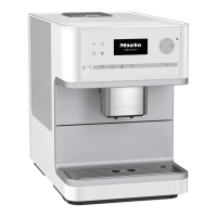
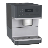
Figure C-1: CM 61x0 ......................................................................................................... 7
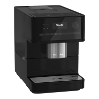
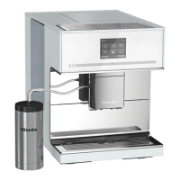
Figure C-2: CM 63x0 ......................................................................................................... 8
Figure D-1: CM 61x0 Component Layout ....................................................................... 10
Figure D-2: CM 63x0 Component Layout ....................................................................... 11
Figure 001-1: Optical Interface Location ......................................................................... 12
Figure 001-2: Water Path Overview ................................................................................ 12
Figure 001-3: Water Path for Coffee ............................................................................... 13
Figure 001-4: Water Path for Hot Water (CM 63x0) ........................................................ 14
Figure 001-5: Hot Milk ..................................................................................................... 14
Figure 001-6: Milk Froth .................................................................................................. 15