Technical Information
15
KF 18xx/19xx
2 Function
2.1 Electrical Supply
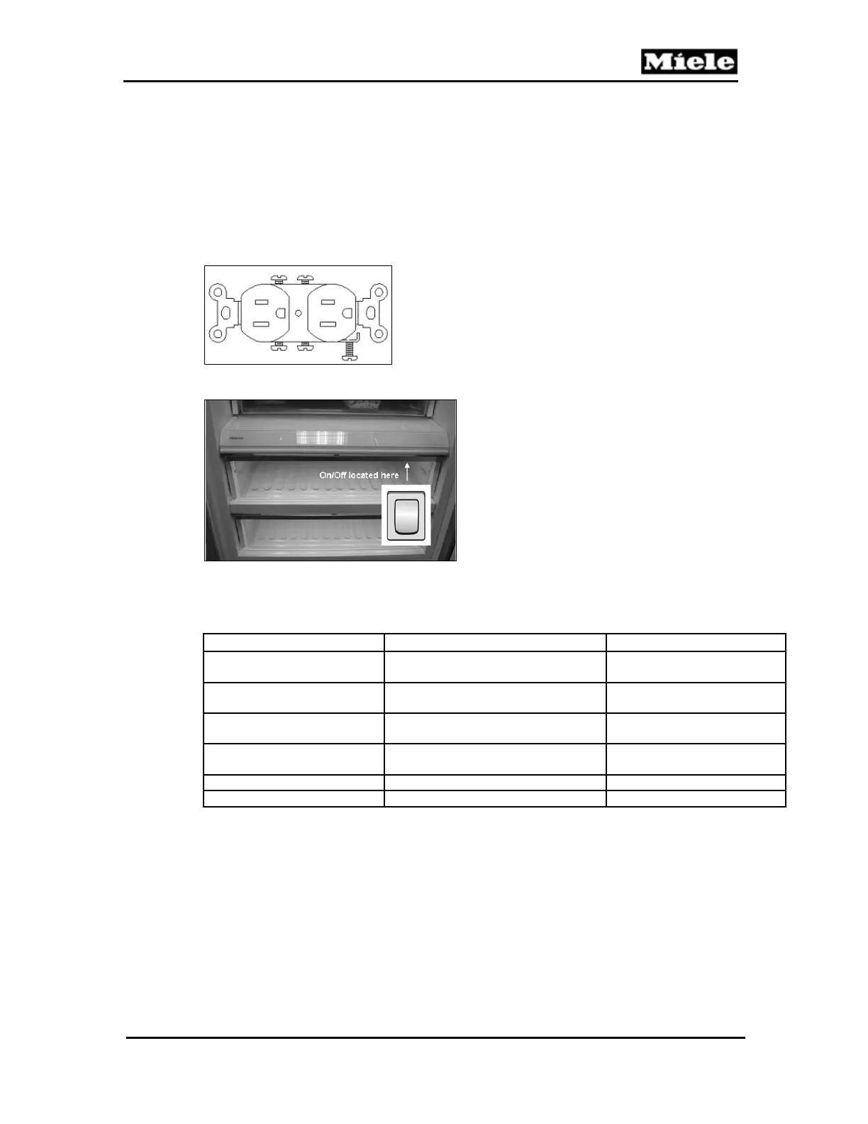
Each appliance will be connected to its own 120VAC, 15-amp power supply.
When column units are installed, there will be separate outlets for each
column (see Figure 030-1). Every cooling appliance also has a main power
on/off switch located inside the appliance, under the main control panel. See
Figure 030-2.
Figure 030-1: NEMA 5-15 Outlet
Figure 030-2: Main Power Board with Switch (Sample)
2.2 Temperature Sensors (NTCs)
NTC Location Function
Refrigerator air (R30/1)
Clipped under refrigerator evaporator
cover
Turns refrigerator
compressor on/off
Refrigerator evaporator
(R30/2)
Clipped above refrigerator
evaporator
Stops refrigerator defrost
phase
SmartFresh air (R30/7) In SmartFresh compartment shelf
Turns refrigerator
compressor on/off
Freezer air (R30/3)
Clipped under freezer evaporator
cover
Turns freezer compressor
on/off
Freezer evaporator (R30/4) Clipped above freezer evaporator Stops freezer defrost phase
Ambient air (R30/8) In toekick area, in front of condenser Regulates compressor speed
Table 030-10: NTCs
 Loading...