Technical Information
17
KF 18xx/19xx
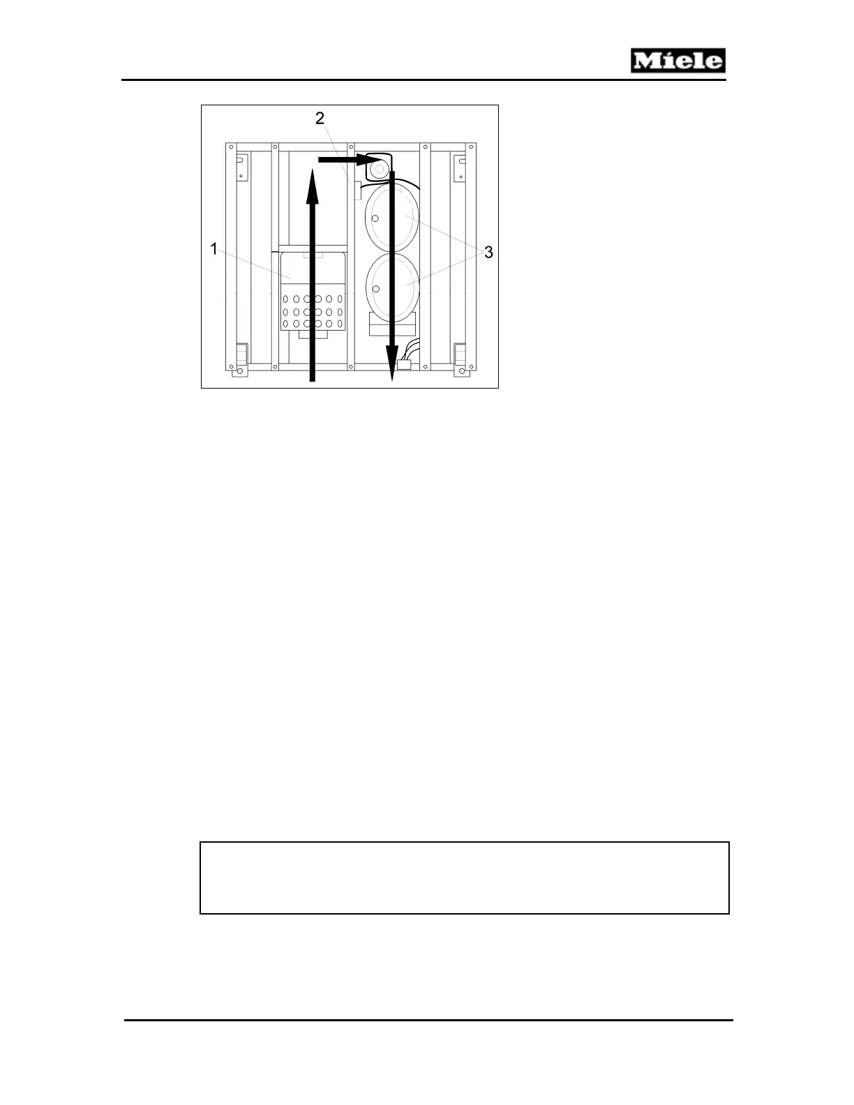
Figure 030-3: Condenser Fan and Components (Top View)
2.7 Refrigerant Stop Valve (Y30/1)
The stop valve enables one compressor to channel R134a (refrigerant) to two
separate evaporators. The outputs are connected to two separate capillary
tubes and evaporators in appliances where more than one evaporator is
needed.
For energy efficiency, the valve works as follows:
Only one output is used on the valve; the other output is factory sealed.
When the compressor stops, the solenoid valve is instantly activated
(closes pathway), storing liquid R134a in the condenser for the next
cooling cycle.
Refrigerant after the stop valve, inside the capillary tube, will slowly
bleed off and continue to cool the evaporator after the compressor
stops.
Stop valve is activated (opens pathway) 12 seconds before the
compressor is switched on. The path to the evaporator is now open
and the stored liquid R134a evaporates without the compressor
being activated.
This valve operation leads to an energy saving of up to 6 percent.
At ambient temperatures above 95°F (35°C) when the network voltage is less
than 107 volts, the compressor start will be delayed by 3 minutes.
At ambient temperatures above 95°F (35°C) and when the network voltage is
less than 107 volts, the compressor start will be delayed by 8 minutes.
Note:
The stop valve is part of the sealed system and cannot be replaced as a
separate part. If it requires replacement, then the entire sealed system must
be replaced.
1 Condenser
2 Condenser fan
3 Compressors
 Loading...