Technical Information
23
KF 18xx/19xx
As ice is defrosted from the evaporator, it drips water into the evaporator pan
below the evaporator (see Figure 030-7). This pan routes the water into the
drain channel (Figure 030-8, Item 1), which is set into Styrofoam in the rear of
the appliance. The water is then routed down the drain channel into a drip
pan, located under the compressor in the bottom of the appliance. The water
collects in this pan and is eventually evaporated by heat from the compressor.
2.21 VCC
®
Compressor
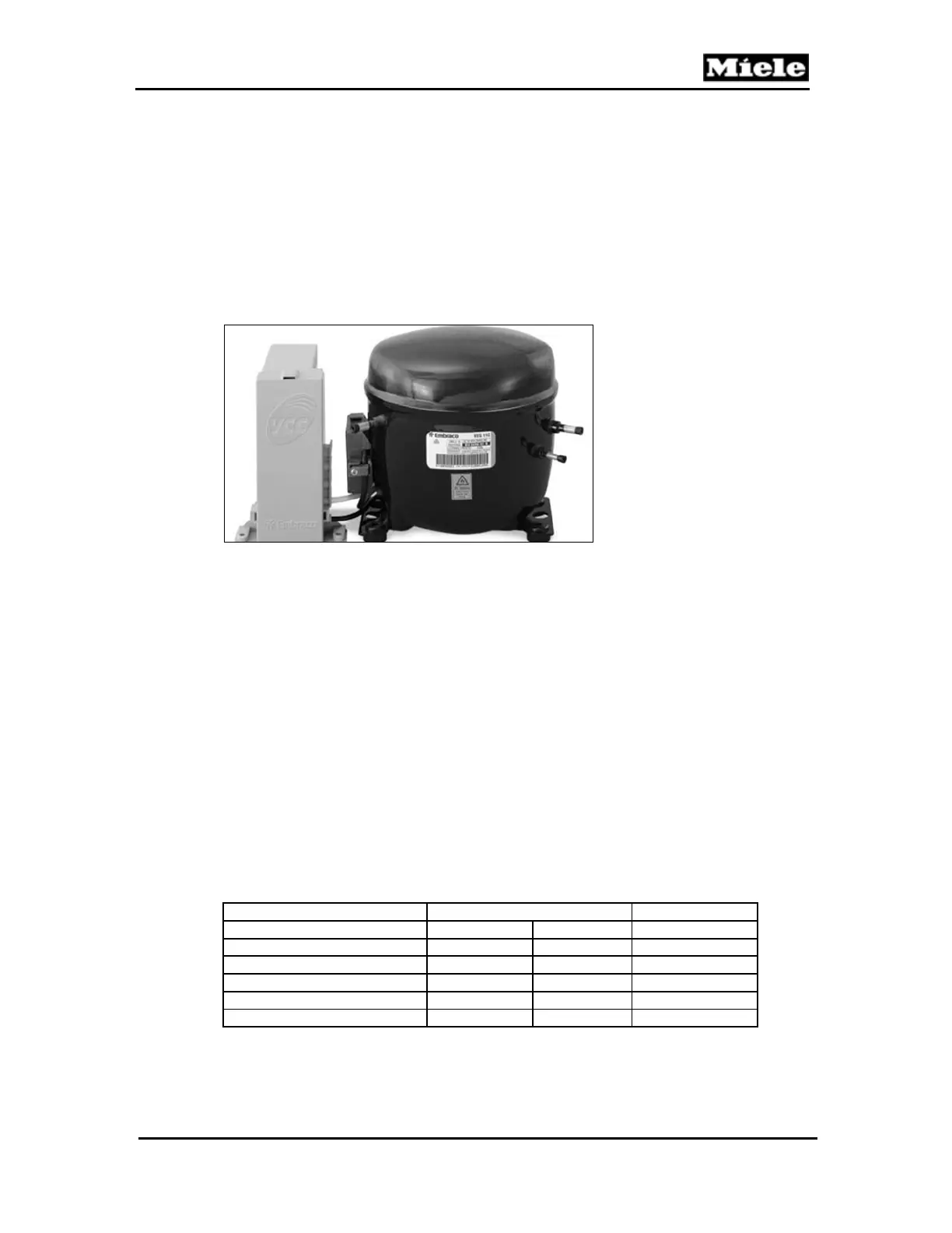
A VCC (variable capacity compressor) is controlled by a frequency control
board mounted next to and wired to the compressor. (See Figure 030-9.)
Figure 030-9: VCC Compressor and Frequency Control Board
The VCC runs at various speeds, depending on the thermal load in the
refrigerator. The compressor stabilizes the temperature in less time than a
conventional compressor. As a result, the compressor uses less electricity
than conventional compressors of the same size. The compressor does not
go through a high-amperage hard start like a relay-driven unit.
The compressor speed is controlled via the ambient-air NTC. The starting
speed depends on the temperature registered by this NTC.
First speed increase:
With compressor operating time longer than 80 minutes, the speed is
increased by 600 rpm. After a defrost phase, the compressor speed is
increased after it has operated for 60 minutes.
Second speed increase:
After a further 30 minutes of compressor operation, the speed is
increased by 800 rpm.
The speed is not reduced while the compressor is operating.
Appliance status Ambient temperature Speed
Normal operation > 98.6°F > 37°C 3500 rpm
Normal operation 95 to 98.6 °F 35 to 37 °C 3000 rpm
Normal operation < 95°F < 35°C 2000 rpm
Super --- --- 4000 rpm
Starting program --- --- 2000 rpm
Defective ambient-air NTC --- --- 3000 rpm
Table 030-14: Ambient Temperature and Compressor Speed
 Loading...