FIGURES
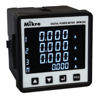
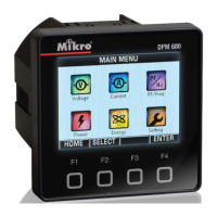
1. Parts of power meter
2. Recommendation cut-out
3. 3-phase 4-wire system with 4 CTs
4. 3-phase 4-wire system with 3 CTs
5. 3-phase 3-wire with 3CTs and 3VTs
6. 3-phase 3-wire with 2CTs and 3VTs
7. Menu map for the normal mode
8. Flow map for the programming mode
2
4
7
8
9
10
13
14
TABLE
1. Parts list
2. Location and part label
3. Model information
4. Specifi cation
5. Data length nomenclature
6. Device and communication register
7. Operation data registers
8. Setting data registers
1
2
3
33
36
37
37
49