Temperature Control Units : MFC with G Series Instrument
Page: 23
Milacron Process Support Business
4165 Halfacre Road Batavia, Ohio 45103
Phone: 513-536-2584
www.milacron.com
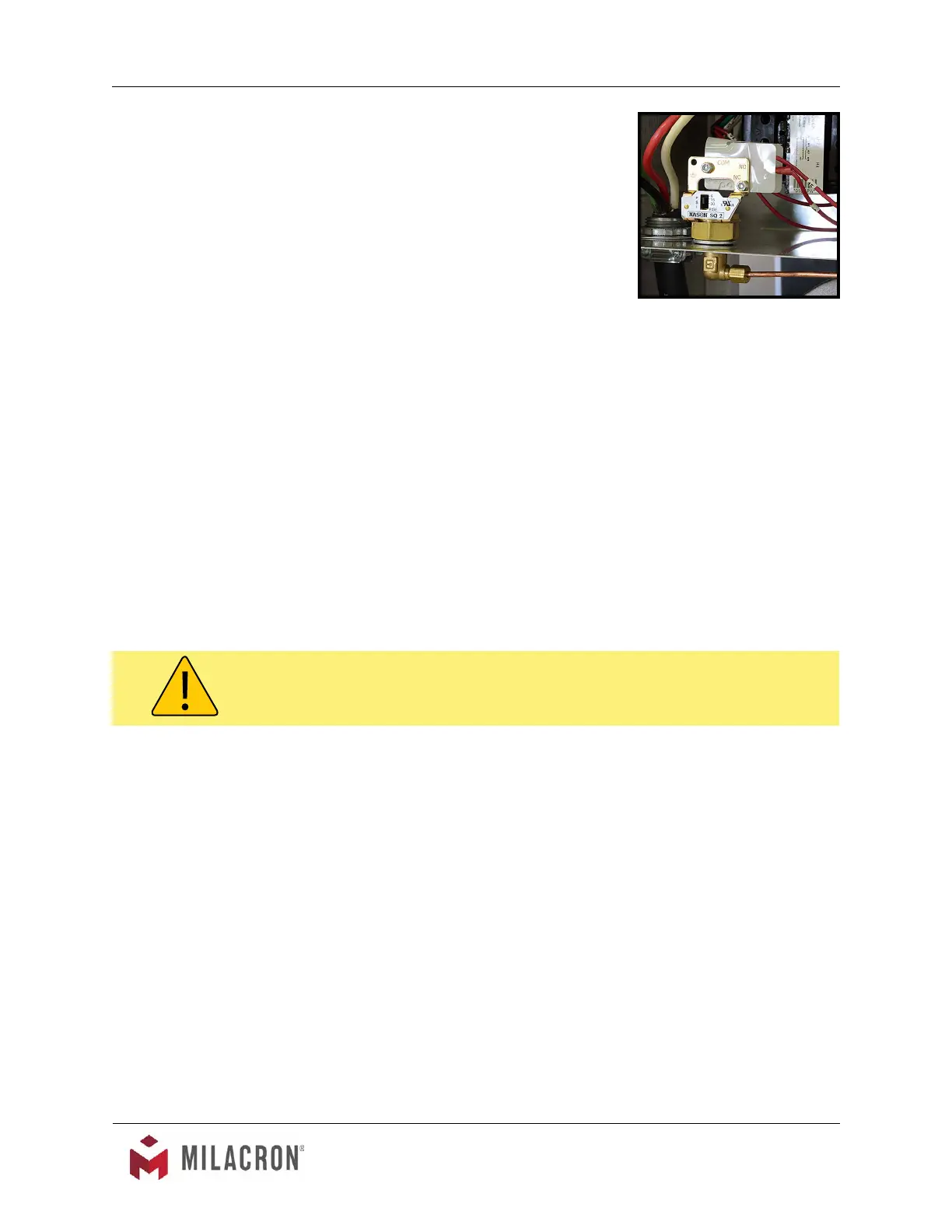
5. Adequate water ll and pressure must be
supplied to the unit for efcient and safe
operation. To ensure sufcient water ll, an
electrical panel mounted pressure switch is
supplied with the unit. A capillary line feeds the
pressure switch. If the water supply pressure
is not adequate the unit can not be operated.
This prevents operation with inadequate water
ll and pressure. If the unit is operated without
adequate water ll and pressure, the unit may
be susceptible to overheating and could result
in unit damage and/or serious injury to operating
personnel.
B. Electric Motor Phasing (Pump Rotation)
1. The operator must determine the electric motor is phased correctly. This is done
by visually inspecting the rotation of the motor shaft as outlined below. Incorrect
phasing of the unit results in poor operation and eventual damage.
a. Supply electrical power to the unit by engaging the unit’s disconnect
switch. Once the correct voltage is supplied to the unit, the Power light
on the display will illuminate.
b. Remove the thermoformed cover panel and open the hinged electrical
cabinet panel cover. Note that the electrical power is engaged at this
point and caution must be observed while the electrical supply is
engaged and the cabinet panel is open.
c. Locate the electric motor and identify the motor shaft inside the electric
motor housing. The motor shaft can be seen through the vent slots in the
motor housing or by removing the shaft cover.
d. Toggle the On / Off switch. This will cycle the motor “on” and then “off”.
e. Observe the motor shaft as it slows to a stop to identify the rotation.
Correct rotation is “clockwise”, when viewed from the rear of the motor.
Incorrect rotation is “counter-clockwise” when viewed from the rear of the
motor. If the shaft does not rotate when the unit is started, the operator
must identify the cause as outlined in this manual’s troubleshooting and
repair section.
f. If the unit is phased correctly, continue with the start up procedure at
step C. If the unit is phased incorrect, continue with step 2.
2. To correct unit phase:
a. Disengage the electrical power supply to the unit at the unit’s disconnect
Typical Panel mounted pressure
switch
WARNING: Electrical power is engaged and caution should be employed while the cabinet is
open.