Temperature Control Units : MFC with G Series Instrument
Page: 24
Milacron Process Support Business
4165 Halfacre Road Batavia, Ohio 45103
Phone: 513-536-2584
www.milacron.com
switch. Follow proper lockout procedures
before proceeding.
b. Once the electrical power supply is
disengaged, reverse any two power leads
of the power cord at the fused disconnect
terminals.
c. Note: The operator must reverse the
power leads at the disconnect only
and not at the power entry terminals
on the unit’s electrical panel. The unit’s
internal electrical system wiring is phased
correctly at the factory and must not be
altered in the eld.
3. To visually verify pump rotation, start the unit and
observe the pressure gauges. The To Process
pressure will indicate 35-50 PSI more than
the From Process pressure. In this state, the
pump rotation is correct (clockwise). If this is
not evident the unit is not correctly phased and
should be corrected as outlined in step 2.
C. Process Flow Adjustments
1. The operator must determine and set proper
water ow rate for the most efcient and trouble
free operation.
a. Water ow rate through the process is
determined by the pressure losses in
the process loop. Generally, higher ow
rates result in turbulent ow achieving
maximum temperature control and lower
maintenance.
b. If the ow rate exceeds the motor HP capacity, the electric motor will
draw excessive amps. This is a result of the process loop’s ability to
ow water at a greater rate than can be provided by the pump. This will
eventually result in tripping the thermal motor overload relay (overload
relays open) and the unit will shut down and illuminate the Safety and
Alarm lights on the display.
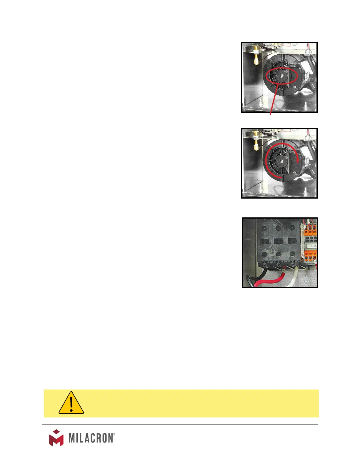
2. If an excessive ow situation is encountered and the motor overload circuit has
tripped, the operator must manually reset the overload relay before operations
can continue. This is done by opening the electrical panel cover and identifying
the overload relay.
DO NOT reverse power leads at the
unit’s power entry.
WARNING: To correct phase ... switch power leads at the disconnect switch only.
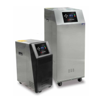
Remove shaft cover to view the
motor shaft.
Correct rotation is clockwise when
viewed from the rear of the motor.
 Loading...