Temperature Control Units : MFC with G Series Instrument
Page: 85
Milacron Process Support Business
4165 Halfacre Road Batavia, Ohio 45103
Phone: 513-536-2584
www.milacron.com
example, if both Temperature Controllers have the same address, they will both
try to ‘talk’ at the same time and garble each other’s data.
4. Verify the network is properly terminated and that it is congured as a ‘multi-
drop’. This is best achieved by following the molding machine manufacturer’s
installation instructions and use extension cables provided by them or us.
5. Attach each device, singly, to the molding machine and see if it ‘talks’. Add
additional devices until a problem is seen.
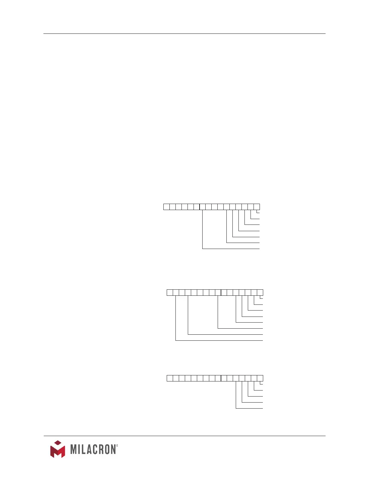
15 14 13 12 11 10 9876543210
PROCESSING
ALARM - SYSTEM
ALARM - PROCESS
ALARM - MACHINE
ALARM - HIGH TEMPERATURE
ALARM - LOW TEMPERATURE
ALARM - LOW FLOW*
CONTROLLER SPI COMMANDS
POLL SELECT
C1 C2 C1 C2 COMMAND DESCRIPTION
20 20 20 21 Echo Controller integrity command
20 20 Version Controller version command
20 30 20 31 Setpoint Desired process temperature
20 32 20 33 High temp Hi temperature deviation alarm
20 34 20 35 Low temp Low temperature deviation alarm
20 36 20 37 Flow Alarm Low flow alarm setpoint*
20 40 Status Process
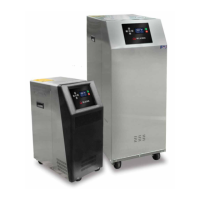
15 14 13 12 11 10 9876543210
PROCESSING
ALARM - SYSTEM
ALARM - PROCESS
ALARM - MACHINE
ALARM - HIGH TEMPERATURE
ALARM - LOW LOW PRESS
ALARM - HIGH CURRENT
ALARM - PHASE
POLL SELECT
C1 C2 C1 C2 COMMAND DESCRIPTION
20 42 Status Machine 1
15 14 13 12 11 10 9876543210
PROCESSING
ALARM - SYSTEM
ALARM - PROCESS
ALARM - MACHINE
ALARM - SENSOR
POLL SELECT
C1 C2 C1 C2 COMMAND DESCRIPTION
20 44 Status Machine 2