OM-272476 Page 7
SECTION 3 − SPECIFICATIONS
3-1. Features And Benefits
LVCt Line Voltage Compensation is circuitry that keeps the power source output constant regardless of input power fluctuation.
Wind Tunnel Technologyt circulates air over components that require cooling, not over electronic circuitry, which reduces contaminants and im-
proves reliability in harsh welding environments.
Fan-On-Demandt cooling system operates only when needed, reducing noise, energy use and the amount of contaminants pulled through the ma-
chine.
Thermal Overload Protection automatically shuts down the unit, only when necessary to prevent damage to internal components if the duty cycle
is exceeded or air flow and cooling are restricted (see Section 3-7).
Auto Remote Sense enables the unit to automatically sense the connection of a remote control. Operation of the remote control is dependent on the
Mode Switch Setting (see Section 5-2).
Lift-Arct TIG starts provide a contamination free weld without the use of high frequency in the Lift-Arc TIG Welding Mode (see Section 6-3).
Adaptive Hot Startt for Stick increases the output amperage at the start of a weld, eliminating electrode sticking in CC and Stick Welding Modes
(see Sections 8-2 and 8-3).
3-2. Arc Controls
DIG control allows the arc characteristics, soft versus stiff, to be changed for specific applications and electrodes in Stick Welding Modes (see Sections
8-2 and 8-3).
Inductance control influences the arc stiffness, bead width and appearance, and puddle fluidity in MIG Welding Modes (see Section 7-2).
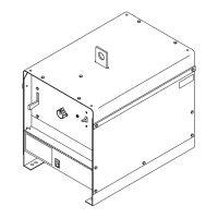
3-3. Serial Number And Rating Label Location
The serial number and rating information for this product is located on the rear panel. Use rating label to determine input power requirements and/or
rated output. For future reference, write serial number in space provided on back cover of this manual.
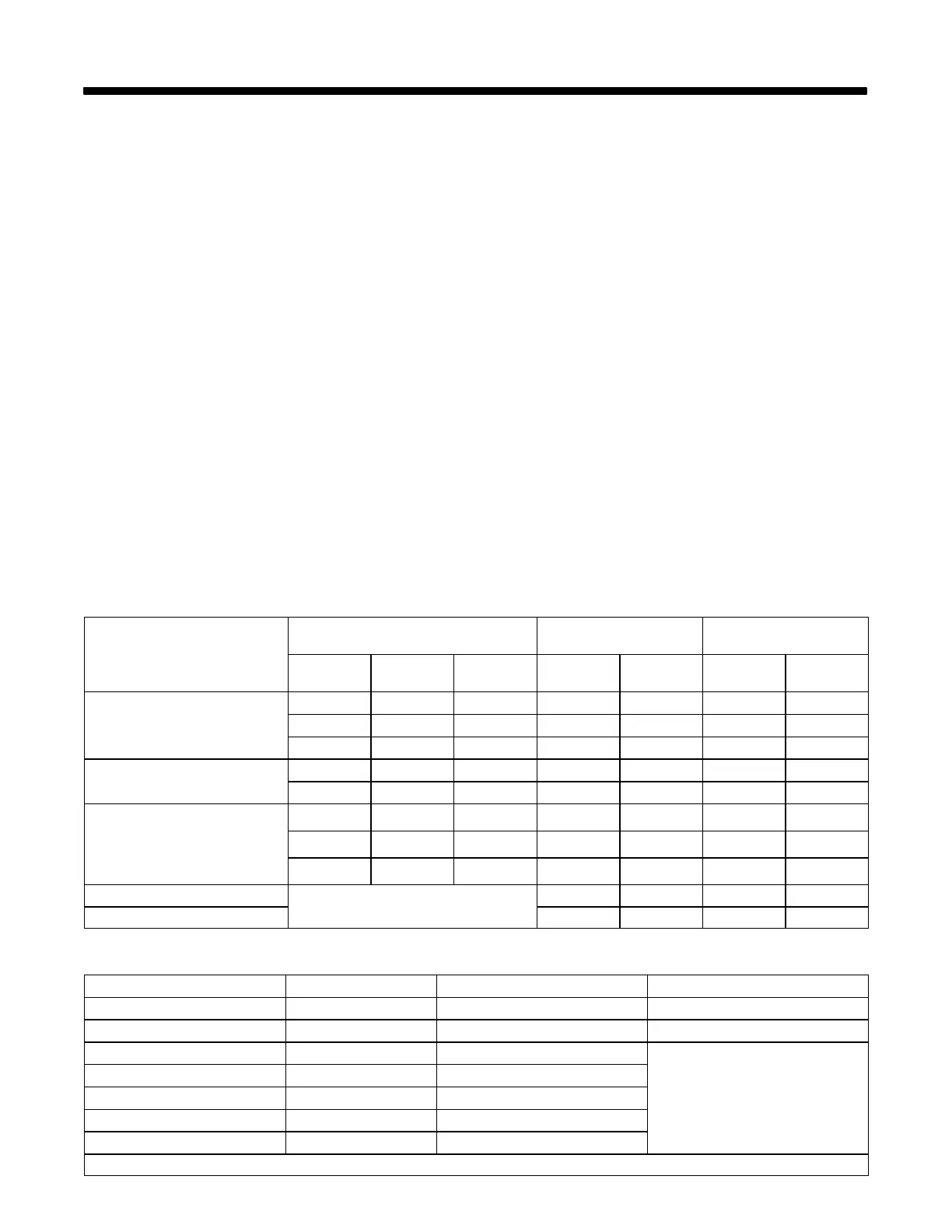
3-4. Unit Specifications
. Do not use information in unit specifications table to determine electrical service requirements. See Sections 4-7 and 4-8 for information on con-
necting input power.
A. Input Voltage And Current At Rated Output
Process
Output Ratings
Amperes Input At Rated
Output (50/60 Hz)
Input Power
(Three Phase)
Current
(Amperes)
Voltage
(DC)
Duty Cycle
(%)
380 VAC 400 VAC KW KVA
GTAW (Lift-Arc TIG)
GTAW (TIG)
650 34 100 39.1 37.4 24.2 25.8
750 34 60 45.3 43.2 28.2 29.8
815 34 25 49.4 46.9 30.6 32.5
SMAW (Stick)
650 44 100 49.9 47.4 30.9 32.8
750 44 60 57.9 55.0 35.8 38.2
GMAW/FCAW (Gas)
FCAW-S (No Gas)
SAW (Subarc)
CAC-A (Gouge)
650 44 100 49.9 47.4 30.9 32.8
750 44 60 57.9 55.0 35.8 38.2
815 44 25 63.5 60.2 39.1 41.8
Idle (Fan Off)
N/A
0.32 0.39 0.055 0.21
Idle (Fan On) 0.45 0.53 0.152 0.37
B. Output Range
Process Output Range Low Open Circuit Voltage (U
o
) Rated No-Load Voltage (U
o
) − OCV
GTAW (Lift-Arc TIG) 10A−815A N/A 12
GTAW (TIG) 10A−815A 12* 63
SMAW (Stick) 30A−815A 12*
65
CAC-A (Gouge) 30A−815A 12*
GMAW/FCAW (Gas) 10V−44V N/A
FCAW-S (No Gas) 10V−44V N/A
SAW (Subarc) 10V−65V N/A
*See Section 5-3 for more information on Optional Low Open Circuit Voltage Mode.