OM-272476 Page 24
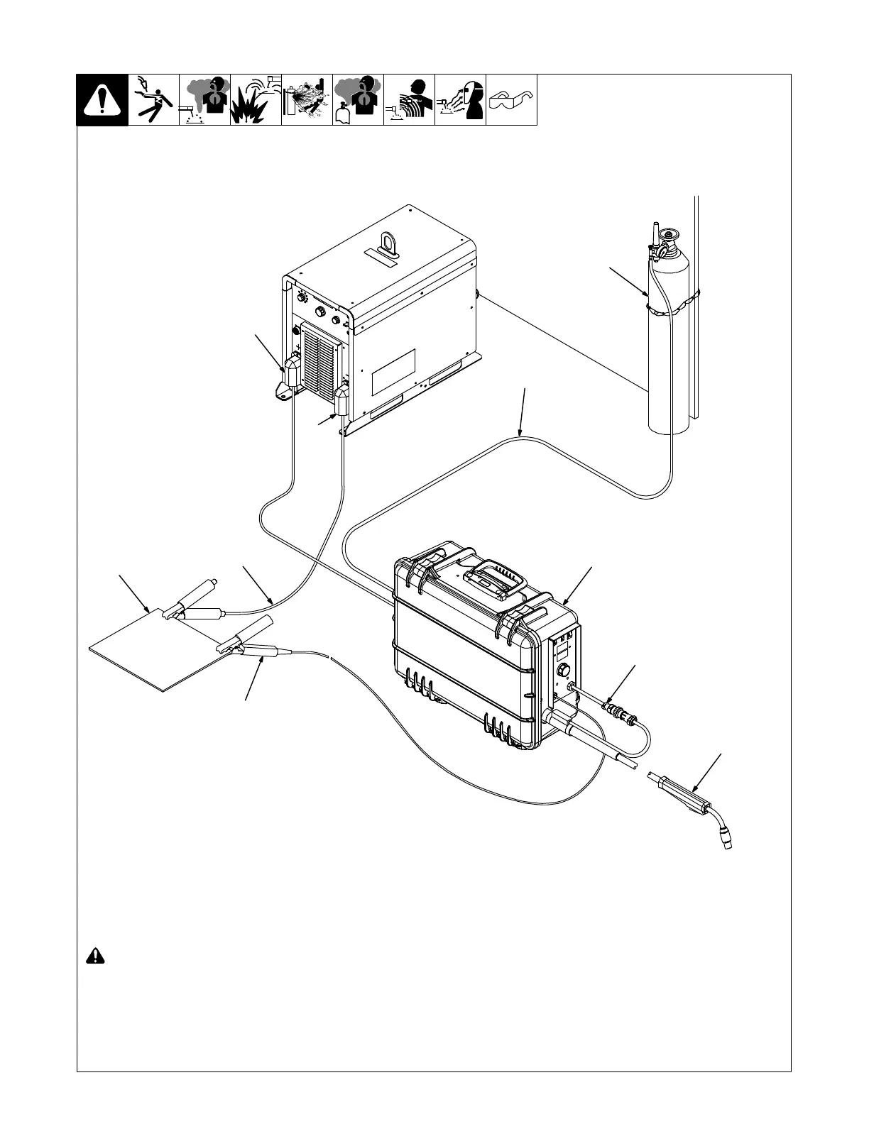
7-3. Typical Connection For Voltage-Sensing Feeder GMAW/FCAW Process
! Turn off power before making con-
nections.
1 Positive (+) Weld Output Terminal
2 Negative (−) Weld Output Terminal
3 Ground Cable to Workpiece
4 Workpiece
5 Voltage Sensing Clamp
6 Gun
7 Gun Trigger Receptacle
8 Wire Feeder
9 Gas Hose
10 Gas Cylinder
Use of shielding gas is dependant on Wire
Type.
. The connection diagram illustrates
DCEP (reverse polarity) suitable for all
wires except self-shielded FCAW. The
majority of self-shielded FCAW wires
require DCEN (straight polarity).
4
269 324-A
3
1
2
5
9
8
7
6
10