. A complete Parts List is available at www.MillerWelds.com
OM-253392 Page 16
SECTION 5 − INSTALLATION
! Do not move or operate unit
where it could tip.
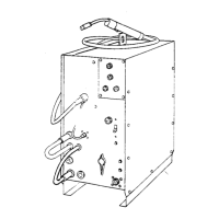
5-1. Selecting a Location
loc_small 2018-08
! Special installation may be
required where gasoline or
volatile liquids are present −
see NEC Article 511 or CEC
Section 20.
1 Lifting Handle
Use handle to lift unit.
2 Line Disconnect Device
Locate unit near correct input
power supply.
Movement
Location And Airflow
2
18 in.
(460 mm)
18 in.
(460 mm)
1
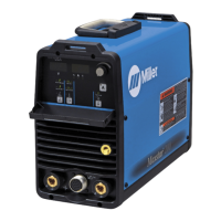
5-2. Stick Welding Connections
Ref. 254 251-B
! Turn off unit and disconnect
input power before making
connections.
! Do not use worn, damaged,
undersized, or repaired
cables.
1 Positive Weld Output
Receptacle
2 Negative Weld Output
Receptacle
3 Stick Electrode Holder And
Cable
4 Work Clamp And Cable
Connect stick electrode holder
cable to the positive weld output
receptacle, and connect work
clamp to negative weld output
receptacle.
Ensure all connections are tight.
4
1
2
3