. A complete Parts List is available at www.MillerWelds.com
OM-253392 Page 17
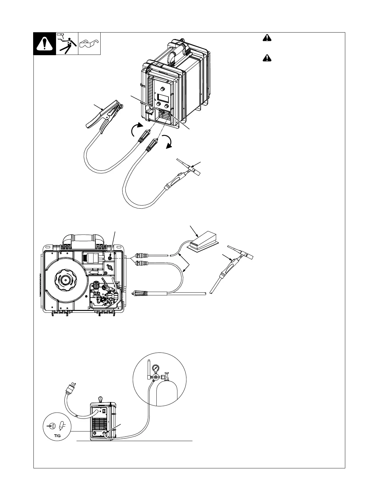
5-3. TIG Welding Connections DCEN (Direct Current Electrode Negative)
Ref. 254 251-B / Ref. 254 249-C / Ref. 254 247-B
! Turn off unit and disconnect
input power before making
connections.
! Do not use worn, damaged,
undersized, or repaired
cables.
1 Positive Weld Output
Receptacle
2 Negative Weld Output
Receptacle
3 TIG Torch And Cable
4 Work Clamp And Cable
Connect TIG torch cable to the
negative weld output receptacle
and connect work clamp to positive
weld output receptacle.
Ensure all connections are tight.
5 Foot Control
6 Finger Tip Control
7 Remote Control Cable
8 Six Pin Remote Control
Receptacle
Route control cable through MIG
gun hole.
Connect foot control or finger tip
control to six pin remote control
receptacle.
9 TIG Shielding Gas
Connection
Use Argon gas for TIG welding (see
Section 5-7).
2
1
3
4
9
5
8
6
7