. A complete Parts List is available at www.MillerWelds.com
OM-253392 Page 25
input4 2012−05 − 803 766-C
! Installation must meet all National and
Local Codes − have only qualified per-
sons make this installation.
! Disconnect and lockout/tagout input
power before connecting input con-
ductors from unit. Follow established
procedures regarding the installation
and removal of lockout/tagout
devices.
! Always connect green or green/yellow
conductor to supply grounding termi-
nal first, and never to a line terminal.
NOTICE − The Auto-Line circuitry in this unit
automatically
links the power source to the
primary voltage being applied, either 115 or
230 VAC.
See rating label on unit and check input volt-
age available at site.
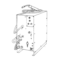
1 Input Power Cord
2 Disconnect Device (switch shown in the
OFF position)
3 Disconnect Device Grounding Terminal
4 Disconnect Device Line Terminals
5 Black And White Input Conductor (L1
And L2)
6 Green Or Green/Yellow Grounding
Conductor
Connect green or green/yellow grounding
conductor to disconnect device grounding
terminal first.
Connect input conductors L1 and L2 to dis-
connect device line terminals.
7 Over-Current Protection
Select type and size of over-current
protection using Section 5-10 (fused
disconnect switch shown).
8 Receptacle (NEMA 6-50R)
Customer Supplied
Close and secure door on disconnect device.
Remove lockout/tagout device, and place
switch in the On position.
5-13. Connecting 1-Phase Input Power For 230 VAC (Continued)
Notes
Work like a Pro!
Pros weld and cut
safely. Read the
safety rules at
the beginning
of this manual.