Page 30/36
Page 30/36
Page 30/36
Figure 1
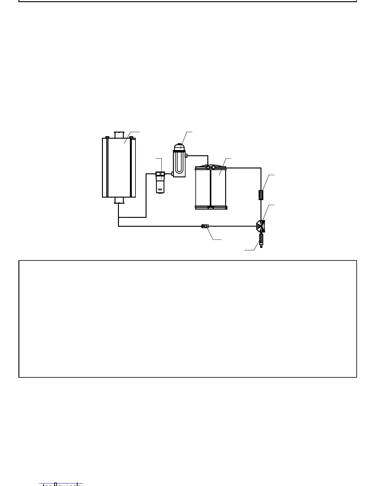
The water flow schematic of the Simplicity is shown below. Only the main components are shown.
Reservoir 1
Pump 2
* UV Lamp 3
Pak 4
Resistivity cell 5
Point of use with dispensing valve 6
Check valve 7
Final filter 8
* Only present on Simplicity 185.
ILLUSTRATIONS __________________________________________
13
2
8
4
7
5
6
Figure 1
The water flow schematic of the Simplicity is shown below. Only the main components are shown.
Reservoir 1
Pump 2
* UV Lamp 3
Pak 4
Resistivity cell 5
Point of use with dispensing valve 6
Check valve 7
Final filter 8
* Only present on Simplicity 185.
ILLUSTRATIONS __________________________________________
13
2
8
4
7
5
6