EasyManuals Logo

Mindray DC-70 Service Manual

Mindray DC-70
295 pages
To Next Page IconTo Next Page
To Previous Page IconTo Previous Page
Page #142 background imageLoading...
Page #142 background image
9-4 Structure and Assembly/Disassembly
9.3.1 Display (Monitor) Assembly
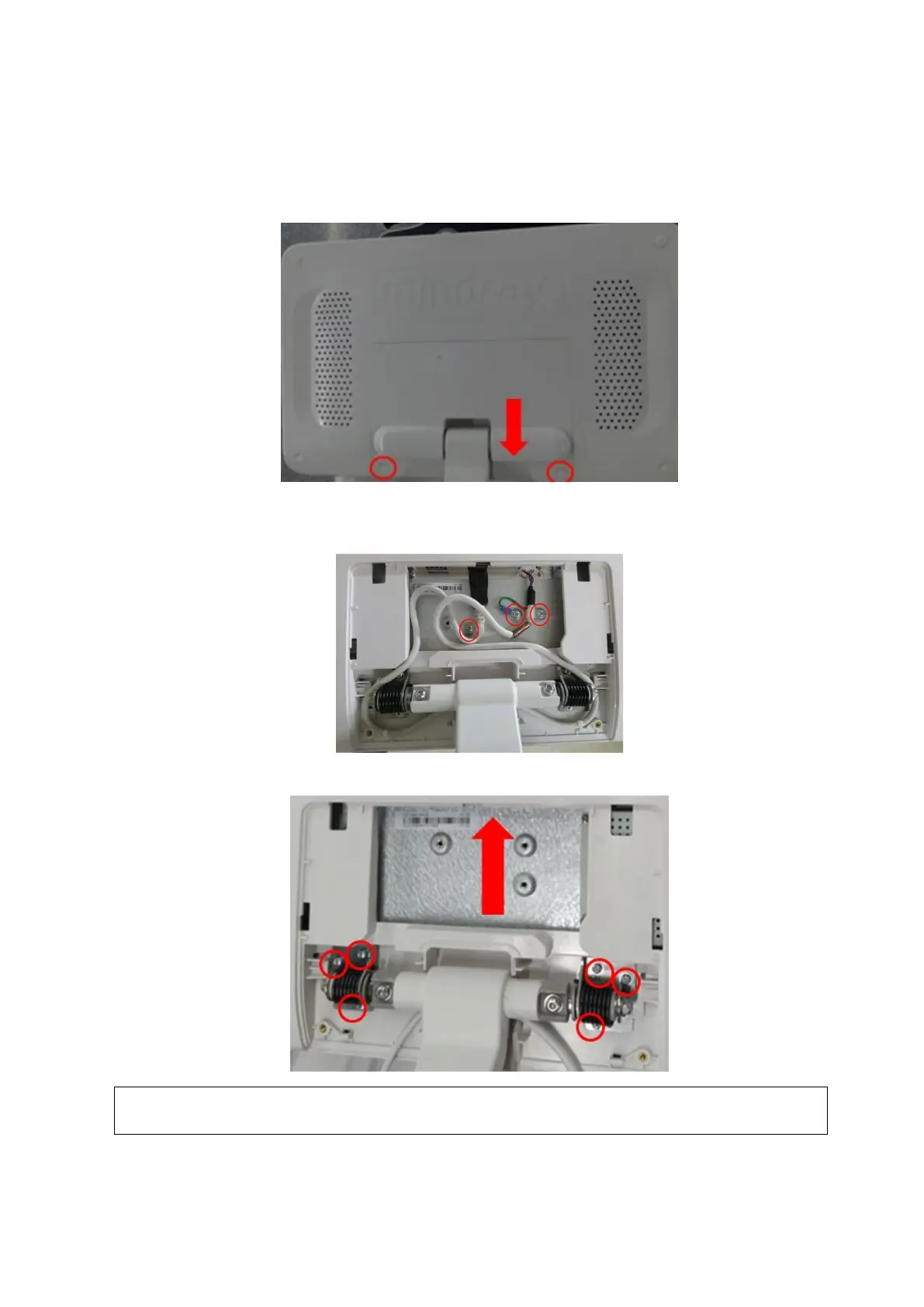
The disassembly tool: cross-headed screwdriver (M3, M4)
1. Unscrew two M4X12 screws, and remove the display cable cover;
2. Unscrew three M4 X 12 screws. Remove the power supply cable of the display and unplug the
signal cable.
3. Unscrew six M4X12 screws, and remove the display assembly upwards.
NOTE:
The metal part is inserted in the hole of the plastic part. The damage of the display’s
rear cover may occur if removed by force.

Table of Contents

Questions and Answers:

Question and Answer IconNeed help?

Do you have a question about the Mindray DC-70 and is the answer not in the manual?

Mindray DC-70 Specifications

General IconGeneral
Power Supply100-240V AC, 50/60Hz
Imaging ModesB-mode, M-mode, Color Doppler, Power Doppler, Pulsed Wave Doppler, Continuous Wave Doppler
ProbesConvex, Linear, Phased Array, Volume
ConnectivityUSB, Ethernet, VGA
Advanced Features3D/4D Imaging
ApplicationsAbdominal, Obstetrics, Gynecology, Cardiac, Small Parts, Vascular, Musculoskeletal, Urology
WeightApprox. 85 kg
Operating SystemWindows-based

Related product manuals