EasyManuals Logo

Mindray DC-70 Service Manual

Mindray DC-70
295 pages
To Next Page IconTo Next Page
To Previous Page IconTo Previous Page
Page #143 background imageLoading...
Page #143 background image
Structure and Assembly/Disassembly 9-5
9.3.2 Probe Board Assembly
The disassembly tool: cross-headed screwdriver (M3, M4)
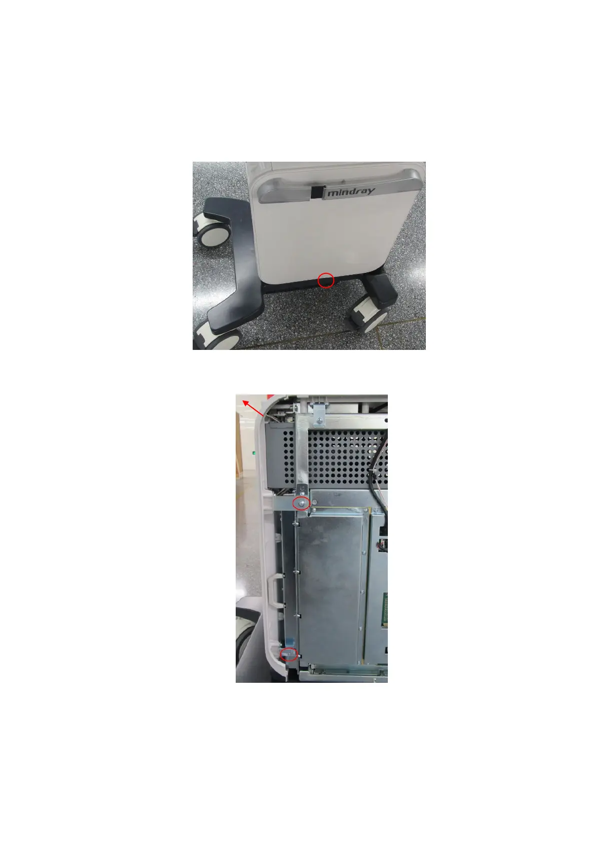
1. Unscrew the M4 X 8 screw on middle part of left side panel’s lower position. Lift the left side
panel upwards to remove it.
2. Follow the procedures of step 1 to remove right side panel.
3. Unscrew two M4 X 8 screws fixing the front cover, and remove the front cover upwards.
4. Unscrew twelve M4 X 8 screws. Hold two plastic handles on the probe board. Pull the probe
board assembly out.

Table of Contents

Questions and Answers:

Question and Answer IconNeed help?

Do you have a question about the Mindray DC-70 and is the answer not in the manual?

Mindray DC-70 Specifications

General IconGeneral
Power Supply100-240V AC, 50/60Hz
Imaging ModesB-mode, M-mode, Color Doppler, Power Doppler, Pulsed Wave Doppler, Continuous Wave Doppler
ProbesConvex, Linear, Phased Array, Volume
ConnectivityUSB, Ethernet, VGA
Advanced Features3D/4D Imaging
ApplicationsAbdominal, Obstetrics, Gynecology, Cardiac, Small Parts, Vascular, Musculoskeletal, Urology
WeightApprox. 85 kg
Operating SystemWindows-based

Related product manuals