EasyManuals Logo

Mindray DC-70 Service Manual

Mindray DC-70
295 pages
To Next Page IconTo Next Page
To Previous Page IconTo Previous Page
Page #179 background imageLoading...
Page #179 background image
Structure and Assembly/Disassembly 9-41
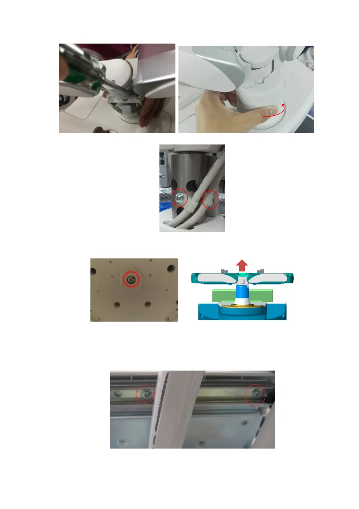
8. Unscrew two M4 X 12 screws, as shown in the following figure.
9. Use an M6 inner hex wrench to unscrew an M10X25 inner hex screw and external teeth lock
washer 10 at the bottom of the minor control board, and uplift and then take out the assemblies
of the supporting arm in the direction as shown in the following figure.
9.3.23 Keyboard Assembly
1. Push and release the keyboard.
2. Unscrew four M4 X 12 screws to remove the keyboard.

Table of Contents

Questions and Answers:

Question and Answer IconNeed help?

Do you have a question about the Mindray DC-70 and is the answer not in the manual?

Mindray DC-70 Specifications

General IconGeneral
Power Supply100-240V AC, 50/60Hz
Imaging ModesB-mode, M-mode, Color Doppler, Power Doppler, Pulsed Wave Doppler, Continuous Wave Doppler
ProbesConvex, Linear, Phased Array, Volume
ConnectivityUSB, Ethernet, VGA
Advanced Features3D/4D Imaging
ApplicationsAbdominal, Obstetrics, Gynecology, Cardiac, Small Parts, Vascular, Musculoskeletal, Urology
WeightApprox. 85 kg
Operating SystemWindows-based

Related product manuals