EasyManuals Logo

Mindray DC-70 Service Manual

Mindray DC-70
295 pages
To Next Page IconTo Next Page
To Previous Page IconTo Previous Page
Page #176 background imageLoading...
Page #176 background image
9-38 Structure and Assembly/Disassembly
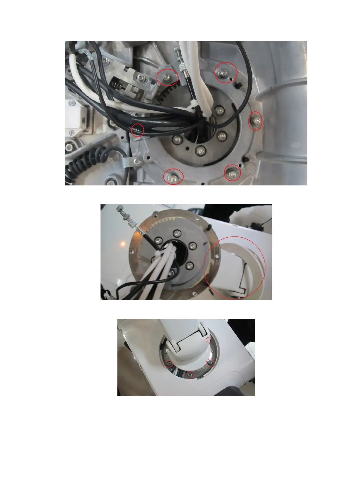
7. Remove the frame of the keyboard. Rotate the white plastic circle on the mechanical arm to
remove the white plastic circle.
8. Unscrew six M6 X 20 screws. Take the data cable out of the inner to remove the support arm
assembly of the control panel.
9.3.22 Support Arm Assembly of the Display
The disassembly tool: cross-headed screwdriver (M3, M4, M10).
1. Unscrew two M4X12 screws, and remove the display cable cover;

Table of Contents

Questions and Answers:

Question and Answer IconNeed help?

Do you have a question about the Mindray DC-70 and is the answer not in the manual?

Mindray DC-70 Specifications

General IconGeneral
Power Supply100-240V AC, 50/60Hz
Imaging ModesB-mode, M-mode, Color Doppler, Power Doppler, Pulsed Wave Doppler, Continuous Wave Doppler
ProbesConvex, Linear, Phased Array, Volume
ConnectivityUSB, Ethernet, VGA
Advanced Features3D/4D Imaging
ApplicationsAbdominal, Obstetrics, Gynecology, Cardiac, Small Parts, Vascular, Musculoskeletal, Urology
WeightApprox. 85 kg
Operating SystemWindows-based

Related product manuals