EasyManuals Logo

Mindray DC-70 Service Manual

Mindray DC-70
295 pages
To Next Page IconTo Next Page
To Previous Page IconTo Previous Page
Page #152 background imageLoading...
Page #152 background image
9-14 Structure and Assembly/Disassembly
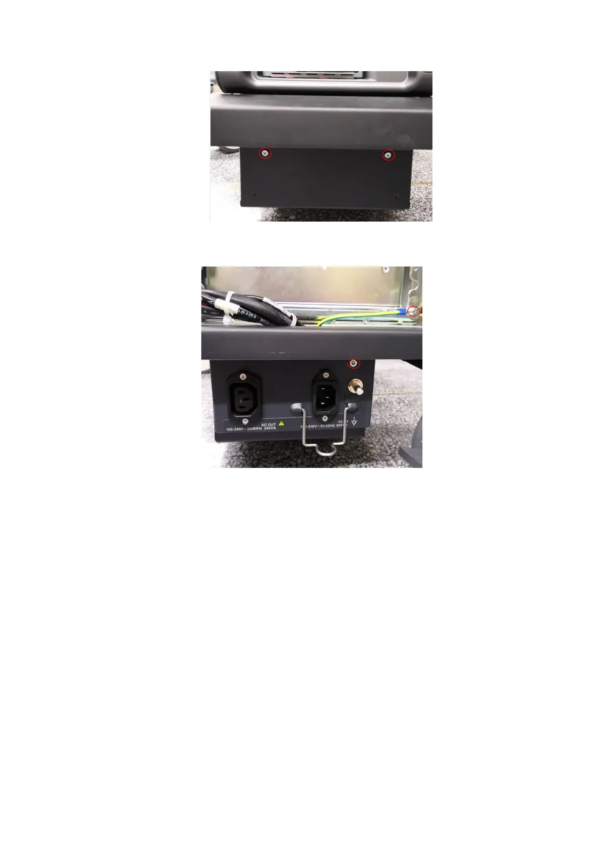
4. Unscrew one M4 X 8 screw fixing the grounding terminal. Unscrew one M4 X 10 inner hex fixing
bolt used to fix the electronic assembly on the base.
5. Pull out the electronic assembly to the location shown in the following figure (do not pull out it
entirely), cut off the three cable ties, remove the three connecting plugs, and then remove the
five M4 X 8 combination screws to disconnect the cables from the electronic assembly.

Table of Contents

Questions and Answers:

Question and Answer IconNeed help?

Do you have a question about the Mindray DC-70 and is the answer not in the manual?

Mindray DC-70 Specifications

General IconGeneral
Power Supply100-240V AC, 50/60Hz
Imaging ModesB-mode, M-mode, Color Doppler, Power Doppler, Pulsed Wave Doppler, Continuous Wave Doppler
ProbesConvex, Linear, Phased Array, Volume
ConnectivityUSB, Ethernet, VGA
Advanced Features3D/4D Imaging
ApplicationsAbdominal, Obstetrics, Gynecology, Cardiac, Small Parts, Vascular, Musculoskeletal, Urology
WeightApprox. 85 kg
Operating SystemWindows-based

Related product manuals