EasyManuals Logo

Mindray DC-70 Service Manual

Mindray DC-70
295 pages
To Next Page IconTo Next Page
To Previous Page IconTo Previous Page
Page #154 background imageLoading...
Page #154 background image
9-16 Structure and Assembly/Disassembly
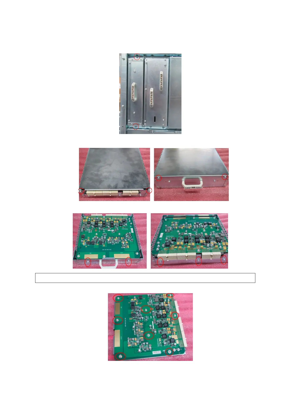
2. Unscrew two M4 X 8 screws on the device (one is on the top; the other is at the bottom). Then,
remove DC box assembly.
3. Unscrew two M3 X 8 screws on both sides to remove the metal cover.
4. Unscrew five M3 X 8 screws on both sides to remove PCBA bracket assembly.
5. Unscrew eight M3 X 8 screws on metal bracket to remove DC board.
NOTE:
Take notice of the bolts on the socket when installing.

Table of Contents

Questions and Answers:

Question and Answer IconNeed help?

Do you have a question about the Mindray DC-70 and is the answer not in the manual?

Mindray DC-70 Specifications

General IconGeneral
Power Supply100-240V AC, 50/60Hz
Imaging ModesB-mode, M-mode, Color Doppler, Power Doppler, Pulsed Wave Doppler, Continuous Wave Doppler
ProbesConvex, Linear, Phased Array, Volume
ConnectivityUSB, Ethernet, VGA
Advanced Features3D/4D Imaging
ApplicationsAbdominal, Obstetrics, Gynecology, Cardiac, Small Parts, Vascular, Musculoskeletal, Urology
WeightApprox. 85 kg
Operating SystemWindows-based

Related product manuals